Guidelines on Technical Specifications Communication tower
January 21, 2019
Comparison of Various Bracing System for Self-Supporting Steel Lattice Structure Towers
February 5, 2019Design of Angle/Tension Type Double Circuit Tower for 110kv Transmission Line
TYPES OF TOWERS
Classification according to number of circuits:
Single Circuit towers
Double Circuit towers
Multi – Circuit towers Classification according to use:
Tangent/Suspension type tower
Angle or Tension or Dead end tower
Transposition tower
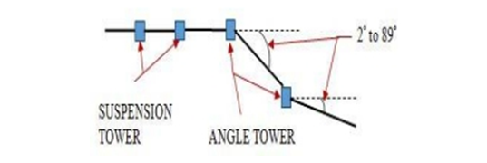
1. Tangent/Suspension type tower:
This type of towers are used along the transmission line where the line is having
angle of deviation 0 – 2° only. They do not carry any loads and are provided just to hold the conductor and earth wire
run through.
2.Angle or Tension or Dead end tower:
This type of towers are used in the transmission line at locations where the line is having angle of deviation more than
2°. These towers will take tension loads and hence are also named as Tension type towers. Tension towers are mostly
used for turning points and for section isolating locations. The piece of the line from one angle tower to other angle is
known as section and length of the section may vary depending on the geographical location. All the towers within the
section are suspension towers with prescribed span length.
Tension towers can further be divided into two categories:
i) Towers due to angle of deviation from 2° to 30°
ii) Towers due to angle of deviation from 30° to 89°
3.Transposition tower:
Transposition towers are used to transpose the conductors of three-phase line. Transposition arrangement is also called
as span transposition. These type of towers are widely used in long transmission lines.
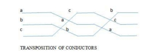
The basic purpose for transposition of transmission line is to rotate the conductors which result in the conductor or a
phase being moved to next physical location in a regular sequence.
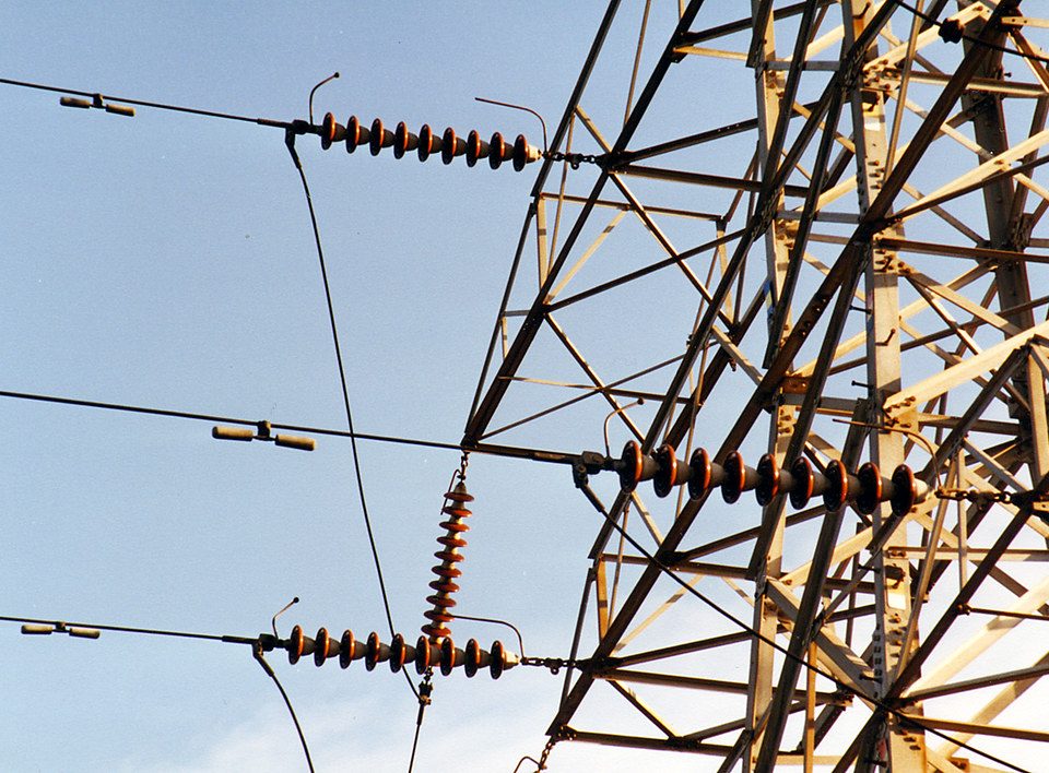
Typical high-voltage overhead transmission lines are composed of bare conductors connected to supporting structures
by means of porcelain, glass, or plastic insulators. The air surrounding the energized conductor acts as the insulating
medium. Maintaining sufficient clearances, or air space, around the conductors to protect the public and utility workers
is paramount to the safe operation of the line. The safety clearance required around the conductors is determined by
normal operating voltages, conductor temperatures, short-term abnormal voltages, wind-blown swinging conductors,
contamination of the insulators, clearances for workers, and clearances for public safety.
Typically, clearances are specified for the following:
• Distance between the energized conductors themselves, communication wires on the same supporting structure, or
between other power or communication wires above or below the conductors,
•Distance from the energized conductors to the ground and features such as roadways, railroads, driveways, parking
lots, navigable waterways, airports, etc.,
• Distance from the energized conductors to buildings and signs, and
• Distance from the energized conductors to other parallel power lines.
TOWER ANALYSIS AND DESIGN
Once the external loads acting on the tower are determined, one proceeds with an analysis of the forces in various members with
a view to fixing up their sizes. Axial force is the primary force for a truss element and therefore, the member is designed for
either compression or tension. When there are multiple load conditions, certain members may be subjected to both compressive
and tensile forces under different loading conditions. Hence, these members are designed for both compression or tension acting
separately.
GEOMETRY OF A 110KV DC TOWER
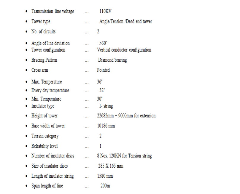
LOAD CALCULATION FOR DESIGN OF 110KV DC TOWER
The self- supporting/suspension towers are rigid in both the directions and it is subjected to two types of live loads i.e.
wind loads acting transversely and longitudinal horizontal loads.
Wind/Transverse loads :
Force due to wind on various elements of transmission lines is obtained by multiplying pressure with the projected
area of that element.
Wind on wire. Fwc … Pd. L. d. Gc. Cdc
Wind on Insulator: Fwi…Pd. Ai. Gi. Cdt
Due to deviation Fwd … 2. T. sin (ɸ / 2)
Longitudinal horizontal loads :
Longitudinal load is due to the weight of conductor and earth wire.
Unit Weight of ACSR Panther conductor =976Kg/Km
For 6 wires of span 200m…6x 0.20 x976 =1171Kg
Weight of Earth wire…1 x 0.20 x 451 =90
Total weight
=1261Kg
Assuming 30% of load only to be transferred (i.e) 378Kg. 500Kg was taken as live load including the weight of
hardware fittings

