Comparison of Various Bracing System for Self-Supporting Steel Lattice Structure Towers
February 5, 2019
Specification of Transmission Line Towers
February 11, 2019Design Examples Power Transmission Towers
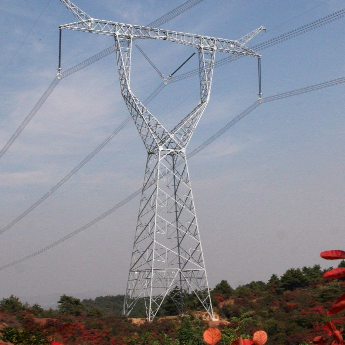
The geometry of tower which is analyzed and design shown in Figure 2 has the base width of tower 7 × 7 m and the height of tower 33.50 m. Tower consist of eight sections,
these are peak of tower, cross arms of tower, cage of transmission tower, common body 0 to 3, and legs of tower. Basic span (distance between two towers) is 305 m, the minimum horizontal and vertical phase to phase is 7.50 m, and 3.85 m respectively, minimum clearance from conductor to ground 7.50 m, cross arm lengths are 7.62 m top, 10.52 m middle and 8.82 m bottom, as shown in Figure 2. The support of tower is rigidly fixed to the foundation of tower.
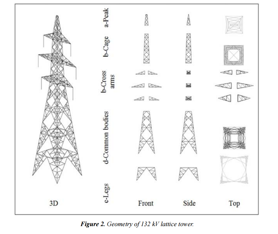
Figure 2. Geometry of 132 kV lattice tower.
The linear and nonlinear simulation are carried out and the analysis results evident that the tower 132 kV double circuit, compared the output data between the linear and nonlinear simulation, it was found that the tower members less prone to the effects during the comparison between them. The difference percentage of maximum element usage between linear and nonlinear analysis type are 0.14 %, 0.46 %, 0.09 %, 0.09 %, and 0.03 %, for KX, K, D, XD, KD, respectively.
The one of basic parameters in the design of tower is weight of tower. The weight of the towers with various bracing system is given in Table 1. The weight of towers designed based on linear and nonlinear analyses are the same.
From output data obtained, the heaviest bracing system is appearing that KX type of bracing system is achieved with a value of 78004.80 N, while the lightest tower is achieved in the D type bracing system with a value of 68272.90 N.

Maximum usage of all members considering the individual members are mainly loaded by axial compression and tension forces, considering all load cases. The member forces are calculated based on three-dimensional linear and nonlinear analysis. The maximum elements usage is listed in Table 1.
In both linear and nonlinear analyses, the critical loading for KX, XD structure type, failure containment loads case (security broken conductor wire at top left cross arm: transverse full wind at +15°C) is critical, for K, D, and KD the failure containment load case (security broken conductor is critical. The critical members which is given in Table 1,
are the same in linear and nonlinear analyses. The all critical members are in compression.
Table 2 shows the results of maximum overturning moments which occur at reliability normal condition loading case (transverse full wind at +15°C, maximum weight span) for linear and nonlinear analyses. In Table 2, the maximum resultant moment occurred at the bracing type KX, which was 7990.115 kN.m and 8035.038 kN.m for linear, and nonlinear analysis respectively. wire at middle left cross arm: transverse full wind at +15°C)

Related posts
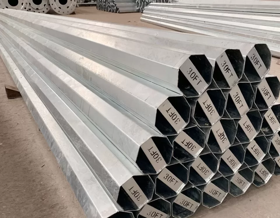
In low-voltage transmission networks, which typically operate below 1,000 volts, galvanized steel poles provide a durable and environmentally friendly solution. This article explores the features, benefits, applications, and technical specifications of low voltage galvanized steel utility poles in transmission line projects.
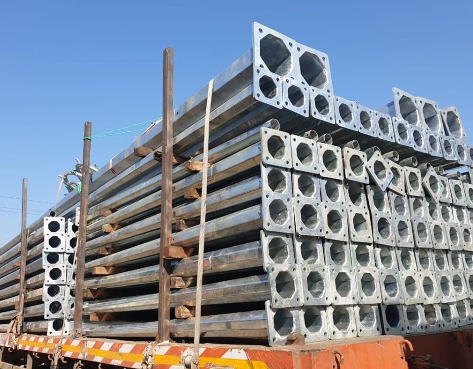
Hot Dip Galvanized Electrical Metal Utility Steel Pole for Railway in Shape Octagonal widely used in electrical power transmission railway station industry. In order to meet the increasingly higher demand for steel poles, our company design and produce many kinds of steel poles for the power transmission and distribution system. Besides, our electrical steel poles have been tested and approved by the Transmission Pole Tower Testing Station.

