132kv,230kv,380kv,400kv Transmission Line Steel Tower Design Loads
April 2, 2018
Power Transmission Angle Steel Tower Assembly Material
April 6, 2018132KV transmission line Galvanized steel lattice tower Detailing and Estimation
Shop Detailing and Estimation
Before leaving the Manufacturer’s Works all tower members shall be hard stamped with distinguishing numbers and/or letters corresponding to distinguishing numbers and/or letters on approved drawings or material lists to be submitted by the Contractor. The erection marks shall be located on the member so that, after assembly and erection, all members can be individually identified.
The erection marks shall be stamped before galvanizing and shall be clearly legible after galvanizing. Care shall be taken to distinguish between various grades of steel.
The erection marks shall incorporate the standard tower nomenclature as given in Clause B1.5.9.
The erection marks shall also incorporate nomenclature to identify all members with increased galvanizing thickness as detailed in Clause B1.5.5.1
All tower connections shall be bolted unless otherwise specified.
If practicable, two bolt holes shall be provided at one end of all diagonal bracing and at all other points where it may be necessary to drift members into place.
Splices shall develop the maximum stresses in members with no credit given for abutting joints. Where lap splices are used, the allowable design stresses shall be decreased by 30 percent. The number of splices shall be the minimum practicable.
Eccentricity of connections shall be reduced to the least practicable value. All web members shall be in one piece where practicable and all double-diagonal web-system members shall be connected at their point of intersection by at least one bolt.
1. Product Name: Power Transmission Tower / Communication Tower
2. Place of Origin: HENGSHUI, China (Mainland)
3. Tower Type: angel steel tower
4. Tower Usage: Communication tower, Lighting rod tower, Radio and television tower, Substation architecture, Telecommunication tower
5. Standard: DIN GB ISO JIS ANSI
6. Material: Usually Q345B/A572, minimum yield strength>=345n/mm2, Q235B/A36, minimum yield strength>=235n/mm2, As well as Hot rolled coil from Q460 ,ASTM573 GR65, GR50 ,SS400, SS490, to ST5
7. Design Height: 20-80m
8. Surface Treatment: Hot-dipped-galvanized following ASTM A123, or any other standard as required
9. Connection Mode: Bolt connection&Welding
10. Rated Voltage Range: 10KV-1000KV
11. Certification: CE, SGS, IAF, CNAS, ISO9001:2015, ISO14001:2004, OHSAS18001:2007
12.Produce Style: Manufacture according to customer’s requirements of drawings or design.
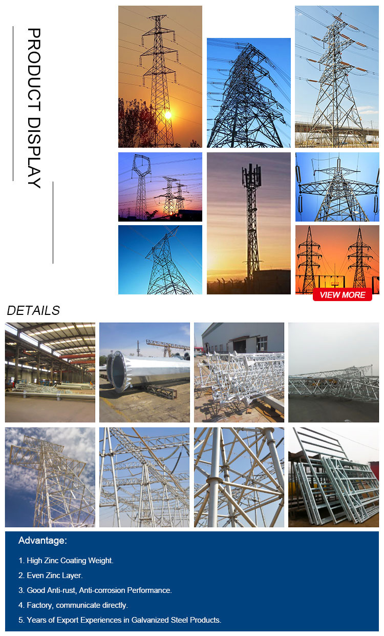
slotted angle iron, galvanized angle bar 5mm, aluminum angle iron, hot dip galvanize angle, perforated angle iron, steel galvanized angle iron, angle iron, hot galvanized angle steel, 45 degree angle iron
Stressed members shall be properly reinforced where the outstanding leg is blocked out.
All members that have an angle up to 30 deg. with the horizontal shall be carefully detailed to insure that personnel will not permanently distort them. A load of 150 kg will be considered for construction or maintenance personnel.
Splices in the legs of towers or extensions shall be located immediately above horizontal members, if possible, or above diagonal brace connections.
The heel of the inside angle of splice angle shall be ground to fit the fillet of the outside angle. Tower members shall have flat surfaces up when practicable.
Plates or other approved means of attaching conductor insulators, shield wire hardware and jumper insulators shall be provided.
Special holes shall be provided for anti-climbing devices, danger signs, tower number signs and tower grounding connections in accordance with the drawings.
All members carrying tension only shall be detailed shorter than the theoretically calculated length. Members 3 m or less in length shall be detailed 3 mm shorter.
Unspliced members more than 3 m in length shall be detailed short by an amount equal to 1.5 mm for each 3 m of length or major fraction thereof plus 1.5 mm, with a maximum of 6 mm.
For tension only spliced members, the amount of draw computed as described above for the overall length shall be increased by an additional 1.5 mm.
The shop details shall indicate the amount by which each member has been shortened.
The Contractor shall pay particular attention to ensuring that all long members are of sufficient section so that after punching they will withstand ordinary rough handling during further fabrication, shipment, unloading and erection.
The spacing of bolts, of various sizes, the edge distances and the minimum sizes of angles shall be as follows (all expressed in mm):
– Diameter of the bolts 12 14 16 20 22 24 27 30
– Distance to the cut-edge in the direction
of the load 20 23 25 30 35 40 45 50
– Distance to the cut-edge in the direction of
the load for splices and hangers of the
cross beam 25 30 35 40 45 50 55 65
– Distance to the edge perpendicular to the
direction of the load 16 18 20 25 27 30 34 38
– Distance between holes 35 40 44 54 59 64 70 80
– Minimum width of the leg of the angle 35 40 45 60 65 70 75 80
The distances to the cut-edge and rolled-edge and between holes are measured from the center of the hole.
Where practicable, the spacing should be not less than three bolt diameters. Edge distances specified above shall not be reduced by under run due to rolling tolerances.
Wherever possible, bolts shall be located so that a socket wrench can be used to tighten the bolt.
Flat washers shall be generally in accordance with BS 4320 of the following thickness:-
– 12 and 14 mm bolts washers 2.5 mm thick
– 16 and 20 mm bolts washers 3.0 mm thick
– 24 and 30 mm bolts washers 4 0 mm thick.

