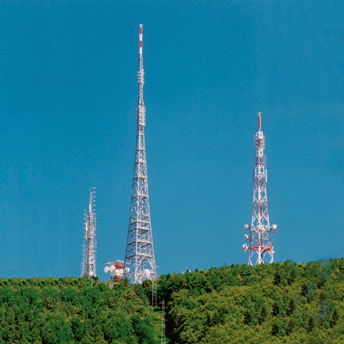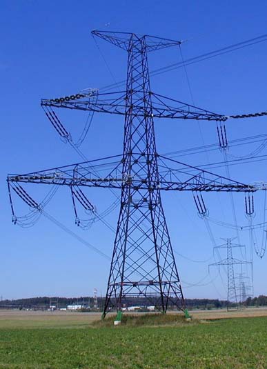
steel lattice tower,transmission tower,power tower
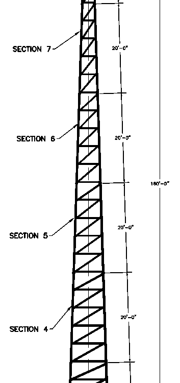
June 15, 2018galvanized per ASTM Standard Self-Supporting Tower 160′
June 20, 201830m self-supporting tower design and manufacture
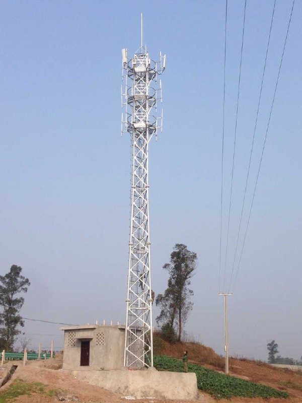
The height of structure shall be 30 m.
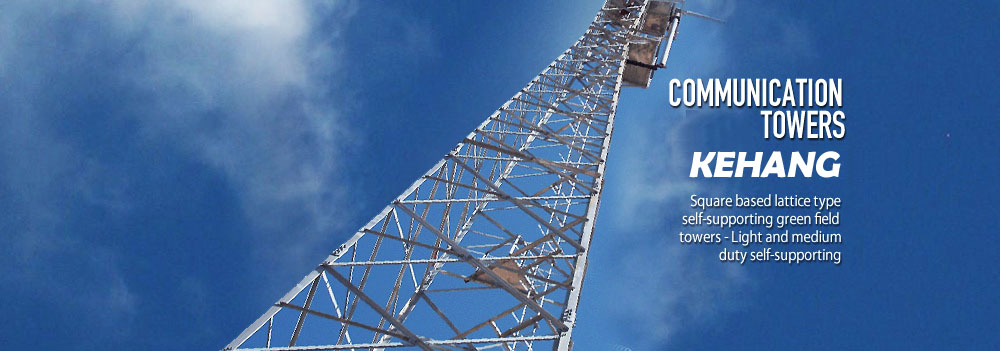
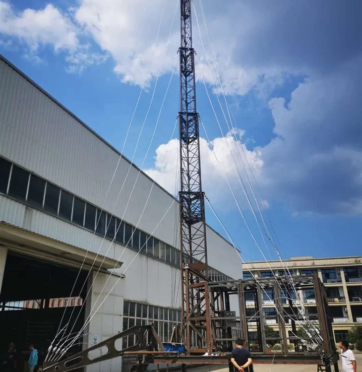
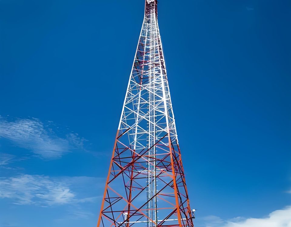
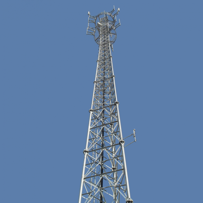
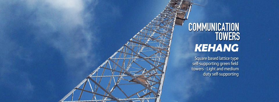
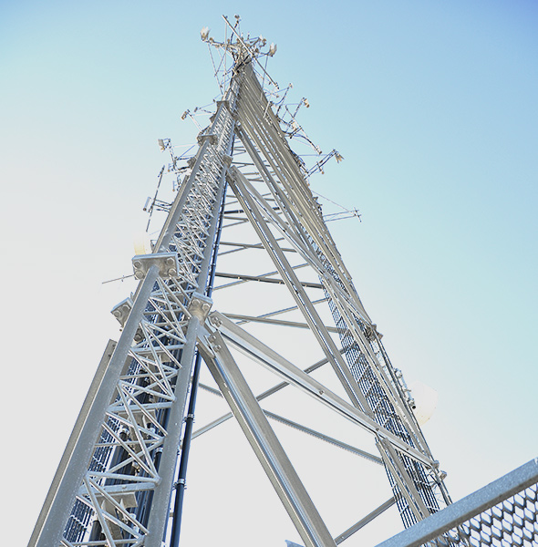
The self-supporting tower shall be 4-legged Angular section type.
The complete tower (legs, web members, base stubs etc) shall be supplied in knocked down condition, to be assembled on site by means of bolts and nuts. Inside the self-supporting tower , a climbing ladder with safety rail shall be provided together with the safety cage. RF cables will run along the climbing ladder fastened to it by means of supports bolted.
For 30 m tower, the base width dimension shall depend on height and its design to meet the overall strength and stability of the completed structure (with Eight numbers of 3.0 m diameter solid parabolic antenna and six sectoral antennas mounted at the top)
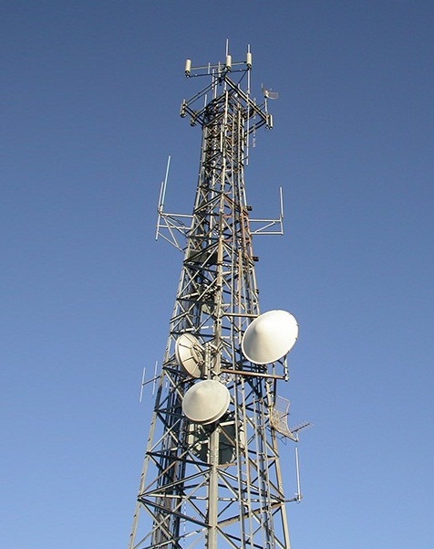
All structural members except required specifically to provide, shall be made of angles. The members/ sections shall be assembled at the time of erection by means of jointing plates, bolts and nuts. No welding of any kind shall be allowed at the sites. The offer shall include all parts required for complete erection of the structure. Nut- bolt, washer and similar minor items shall be provided in excess by 10% of the actual quantity required or minimum one extra for small number, whichever is more for each type.
All members of the structure shall be straight unless required to be curvilinear form, and shall be free from twist and kinks.
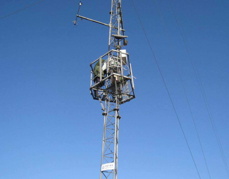
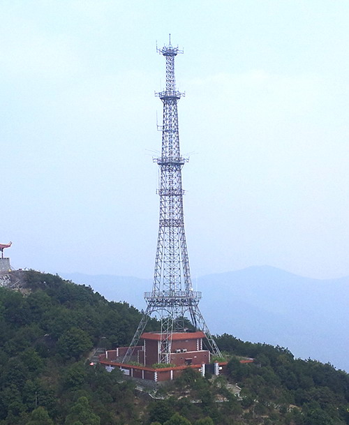
For the 30 m self-supporting tower , internal working platforms, are to be provided at the heights of 12 m (rest platform), 20m (working platform) and 28 m (working platform).
The level of the platform may vary ±0.5 m
Antenna mounting structures for up to 3.0 m diameter solid parabolic antenna at all fours faces/ legs accessible from the internal platforms shall be mounted at each platform except at the top most platform at which a ring type antenna mounting structure for six cellular antennas shall be mounted
Free passage shall be provided through the appropriate edge of every platform to run the RF cables. All the platforms shall have a lockable window for safety and the platform shall cover all the space except ladder and feeder space.
Loading capacity of the platforms shall be more than 200 kg/sq.m.
Platform docking shall be made of expanded metal or similar material adequately supported on steel members of appropriate size.
Platforms shall be provided with handrails at a height of 1.0 meter above the decking, intermediate rails at approx. 0.5 meter above the decking and kick-rails at decking level.
(Lightning Arrestor) of approx. 2.5m with fixing materials at the top of the self-supporting tower so that the top of the omni directional antenna shall be within the umbrella zone of lightening arrestor. The tower and lightning arrestor shall be electrically isolated. A stranded flexible copper wire and having cross sectional area of at least 50 sq.mm shall be supplied. The stranded wire shall be clamped to the lightning rod at one end and the other end to the grounding rod. Minimum length of the copper wire shall be 50 m for 20 m and 30 m tower and 70 m for 50 m tower. The copper wire shall be electrically insulated. The supplier shall supply suitable number of grounding rod and clamps to ground legs of the tower. Installation materials for tower earthing (C-clamps, T- clamps, U-bolts, tie band, Putty tape etc.) shall also be provided. Tower shall be properly grounded in order to achieve the earth resistance value less than 10 ohm, which should be independent from the existing earthing system.
All four legs of the tower shall be connected to the grounding.
In order to ground the feeder cables, required number of earthing bar plates (300 mm X 150 mm X 6mm) with accessories shall be provided. The earthing bar shall be of anodized copper. The Earthling plates shall be connected with 50 sq. mm insulated copper wire. Such type of earthing bar shall be installed at two place of the tower, first one shall be at 1m below the topmost platform and the second one shall be at 1 m above, from the start of the horizontal cable. There shall be separate 50 sq.mm insulated copper wire for the lighting arrestor and earthing
For 30 m tower
Only one horizontal cable ladder of 20 m length and 0.6 m wide in at least five sections each of 4 m long with two vertical supports or as per requirement of the site shall be provided for each supplied 30 m tower. The design of the vertical support shall be such that it can be fixed at point of horizontal ladder and the fixing shall be rigid and not prone to generate vibration. Adequate protection shall be provided against falling object (flat type). . The base of the vertical support shall be fixed to the M20 concrete (1:1.5:3) with appropriate size.
Internal caged ladder shall be provided for each tower, starting the base of self-supporting tower up to the top platform. The base of the climbing ladder with safety rail (wherever applicable) shall be fixed to the M20 concrete (1:1.5:3) base of size 500 mm*600 mm *150 mm.
Loading capacity of the steps shall not be less than 120 kg
Width shall not be less than 40 cm.
Rise of ladder steps not more than 30 cm.
Ladder shall have a continuous safety cage starting from 2m above the ground level, constructed of loops separated by not more than 0.5 m and with not less than 3 vertical back strips. Design and construction shall be such that the ladder cage steps are rigid and not prone to generate vibration. Negative (backward) tilt of the ladders is not allowed.
Convenient and free access to and from the ladder shall be provided at every platform level.
Steps shall be round type with grip of diameter 25 mm.
The ladder shall run up to 1.5m above the top platform.
Fall arrester system
The climbing ladder shall be provided with the fall arrester system for the purpose of safety of climbers.
The fall arrester system shall compromise of
Separate Safety rail
Movable latch with hook
Safety Rail
The safety Rail shall be of Galvanized Steel
The safety Rail shall support the weight of at least 5 (five) People
Movable Latch
Locking Brake pawl shall be provided in the Latch for climber to attach to its harness
The latch shall freely move along the climber in normal climbing position
Fall shall be instantly arrested when a sudden downward motion is applied
If there is slip then latch brake shall remain locked until the force is removed
Foundation Bolts
Foundation bolts/anchor bolts shall be provided for all the self-supporting tower .
There shall be at least two nuts with cap for each bolt.
All structures shall be of bolted construction and shall be designed and manufactured to facilitate transportation to, and assembly at, the sites
The antenna mounting steel work shall be designed to allow a nominal azimuth adjustment of +/- 5° and an elevation adjustment of +/- 5°. In any case sufficient azimuth range is required to verify the 3 dB beam width for the antenna after mounting allowing the direction of the antenna in the case of possible misalignment of the foundation
The supplier shall provide detail load calculation of all the elements and the point of application of such load as follows:
(a) Dead load (b) Live load (c) Wind load
Detailed design of foundation shall be performed by the supplier with soil test and the design to be approved by NT prior to execution of the foundation work.
Separate detail foundation design, drawings with their calculation data sheet shall be submitted for the approval purposes before execution of the foundation work
Steel work
The steel used in fabrication of self-supporting tower shall comply with IS 2830-1992, Grade 410 or equivalent standards for steel metal used in the fabrication of structures. The supplier shall provide weight of the steel used for all types of offered tower.
The wind loading on structures and antennas shall be based on a ground level wind velocity of 170 km.p.h. and increasing with height in accordance with British Standard BSI CP3: chapter V:.
Galvanizing and painting
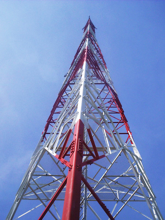
All steel work and fittings used in the assembly of self-supporting tower except those used in concrete foundation, shall be galvanized by the hot dip process after fabrication as per ASTM A 123. The thickness of galvanization shall be more than 500 grams per m2. Steel works forming portion of the foundation shall be galvanized down to a length of not less than thirty [30] cm under the surfaces of concrete. Tower members shall be painted using two different colors as per ICAO standard after galvanization. The paint shall be firmly adherent and shall have outstanding resistant property against water, chemical, brine and crude oil.
Painting or cadmium plating shall not be used in any instance as a sole means protection against corrosion except for repair purposes

