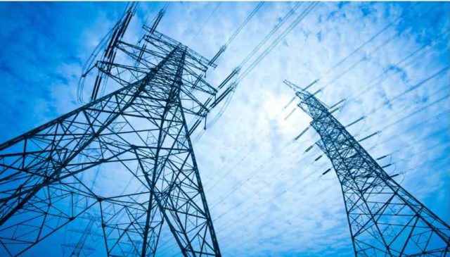
400KV Lattice Steel Tower Design Requirements and Design Spans for Support Locations ,Electric Transmission Line steel
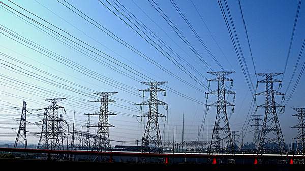
Types of Transmission Line Towers and Configurations – used erect opgw
March 31, 2018
Self-Supporting Steel Lattice Tower Sizing of Tower Members & Conductor Spacing and Clearances
April 1, 2018400KV Lattice Steel Tower Design Requirements and Design Spans for Support Locations ,Electric Transmission Line steel
B1.5.1 Design Requirements
The unit stresses in members and connections for the structural design calculation, based on the design loading and design unbalanced loading (broken wire conditions) multiplied by safety factor indicated herewith shall not exceed the yield stresses according to DIN or BS. Connections shall be designed for the same member forces and according to the above-mentioned standards. The towers shall be designed with an overload capacity (factor of safety) for the unbalanced design loading stipulated in this Specification. No damage or permanent distortion of any members, bolts, connections of fittings or elongation of bolt holes shall be permitted for these design conditions.
- a) The conditions of ambient temperature for maximum working tensions and sags are:
- A temperature of 0ºC with wind loads
- Maximum temperatures of 75ºC in still air.
- The basic wind pressure on structures shall be taken as 86 kg/m2. The factored wind load on the towers shall be calculated in accordance with IEC 60826.- Design Criteria of Overhead Transmission Lines.
- c) The basic wind pressure on conductors and earth wires shall be 52 kg/m² and wind load on a single insulator shall be 60 kg/m². the factored wind load on conductors shall be calculated in accordance with IEC 60826 – Design criteria of overhead transmission lines.
- Design spans shall be as specified for the appropriate type of tower. The weight of insulator strings shall also be considered. The maximum longitudinal tension to be considered is that caused by maximum permissible span being adjacent to minimum permissible span.
- Towers shall be designed to support, at a temperature of 0ºC, the said wind loading on structures and wind loads on conductors, earth wires and insulators strings, applied normal and at 45ºto structures and spans.
- Longitudinal loads shall be considered for earth wires and conductors of suspension and tension towers. See B1.5.13.2
- All double circuit suspension towers shall be designed to support, under the most unfavorable conditions, the overturning and torsion moments resulting from the break of one phase conductor or one earth wire.
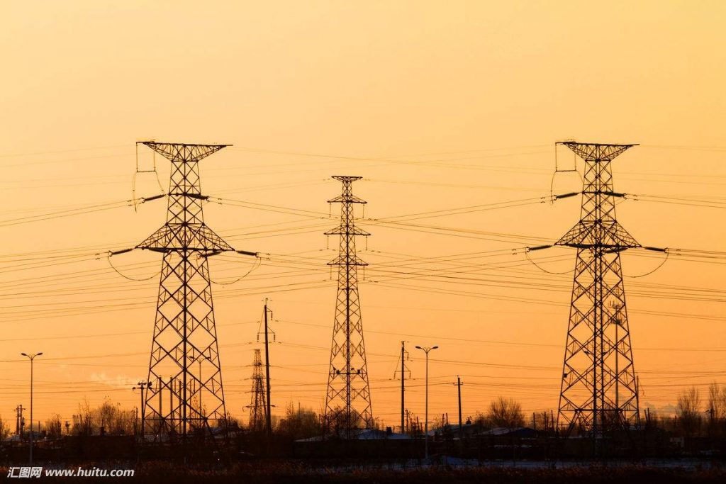
All double circuit medium angle tension towers shall be designed to support, under the most unfavorable conditions, the overturning and torsion moments resulting from the break of any two phase conductors on the same side and in same span, or any one phase conductor and one earth wire on the same side and in same span.
All double circuit large angle tension towers shall be designed to support, under the most unfavorable conditions, the overturning and torsion moments resulting from the break of any three phase conductors on the same side and in same span, or any two phase conductors and one earth wire on the same side and in same span.
Maximum working tension at 0ºC and wind load for conductor, earth wire, insulator strings and structures shall be taken for this load condition. The tension due to broken line conductor(s) on suspension towers may be reduced to 70% of the maximum tension to allow for rotation of insulator strings. Ice loading shall not be considered.
Maximum working tensions at 0ºC with wind load are:
Conductors: 40% of UTS
Optical fiber core earth-wire: 40% of UTS
All towers shall be designed for cascade condition. All wires are to be considered as broken in one span at an everyday tension of 20% UTS in still air at 25ºC.
- The transverse and vertical loads at the conductors and earth wires supports shall be calculated according to the length of the specified spans, the weight and wind. The effects of vertical, transverse and longitudinal loads shall be considered as acting simultaneously and shall be applied normal to one another.
- All towers and their related components shall be capable of resisting any combination of the design basic loads multiplied by a factor of safety of 2 (in normal conditions) and of 1.25 (in broken wire conditions).
- The capacity of all members and connections shall be determined using the allowable stresses set forth by the Contractor and approved by the Engineer.
- All tension members shall be designed on the basis of minimum net sectional area.
- All compression members shall be designed on the basis of gross sectional area. Members are to be properly proportioned to prevent local buckling at loads less than the column carrying capacity.
- Tower members on which man can stand (defined as being up to 30° from horizontal) shall be capable of withstanding on ultimate point load at 1.5kN at any point of the member.
- Load on dead-end structures are those resulting from the assumption that all conductors and shield wires are dead-ended only on one side of the structure at maximum tensions with maximum deviation angle. The outlines of towers shall be in accordance with the drawings included in the Specifications.
- All towers shall be designed to carry line conductors with the associated insulator sets, overhead optical fiber core and galvanized steel shield wires and all fittings under the conditions and within the factors of safety specified. The conductors shall be arranged as shown on the drawings. Conductor stringing procedure shall be provided stating the sequence of conductor erection, and maximum tensions.
B1.5.2 Design Spans for Support Locations
The different tower types indicated in the Specifications/Schedules shall be designed for the basic-, wind-and weight-spans as indicated hereunder. The towers shall be set out on the profile drawings such that the following spans are not exceeded:
|
400 kV Basic Span: 450 m |
Suspension Tower Type A |
Tension Tower Type B |
Tension Tower Type C |
Terminal Tower Type CS |
|
Angle of deviation (deg.) |
0º-2º |
0º-30º |
0º-60º |
0º-60º |
|
Max. sum of adjacent spans (m) |
1080 |
1350 |
1080 |
800 |
|
Maximum single span (m) |
900 |
900 |
900 |
500 |
|
Maximum wind span (m) |
540 |
650 |
540 |
400 |
|
Maximum weight span (m) |
950 |
1400 |
1300 |
900 |
|
Minimum weight span (m) |
200 |
– |
– |
– |
|
Uplift weight span (m) |
– |
– 300 |
-200 |
-100 |

