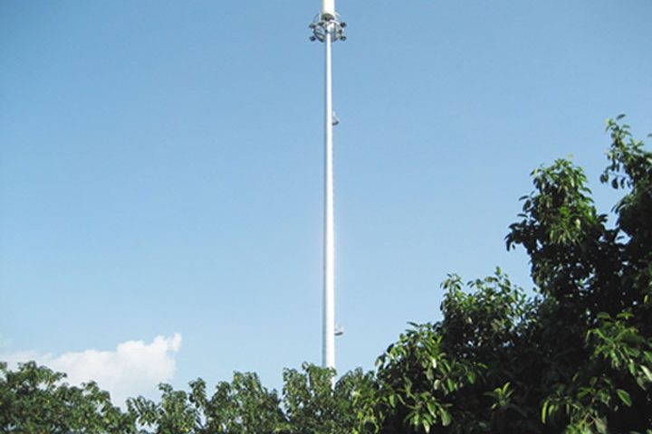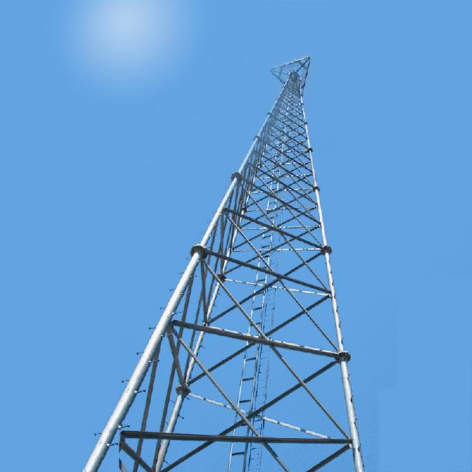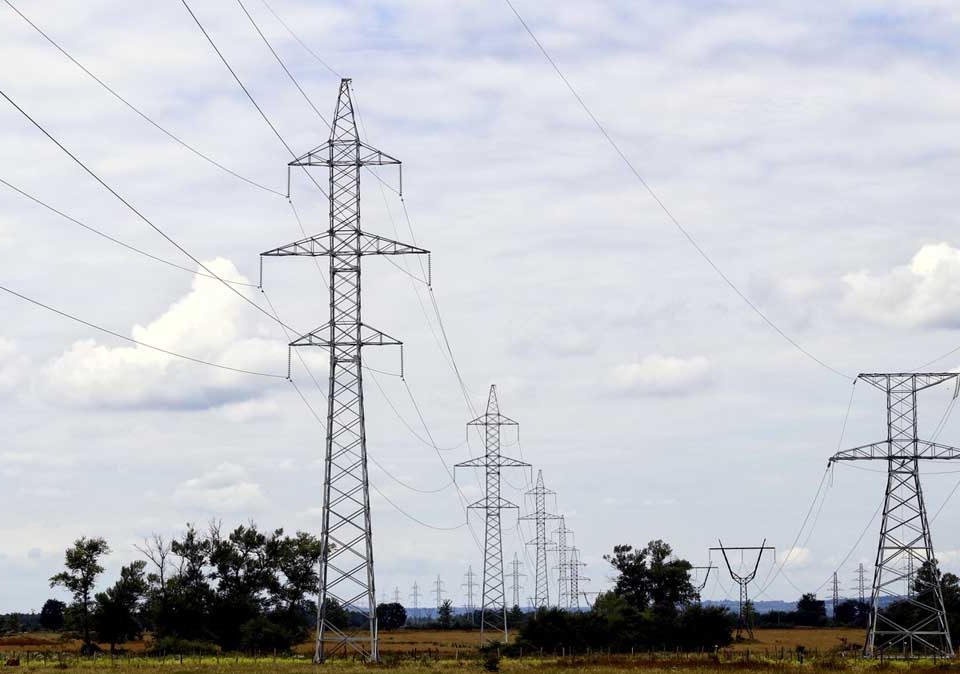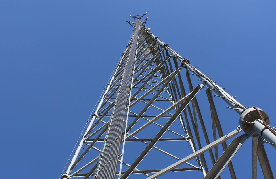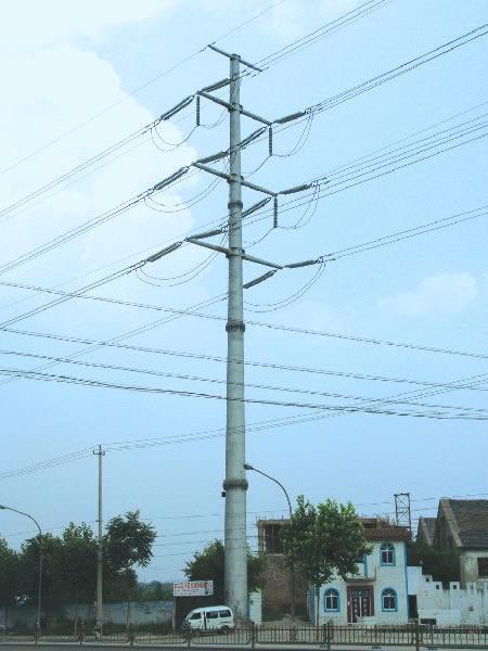
monopole tower communication pole tower
November 18, 2018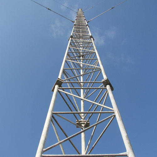
guyed tower VS free-standing tower
November 27, 2018monopole tower type and design span
Monopoles shall have the general arrangements and configurations shown in the drawings included with the attachment. They shall be designed to resist the specified ultimate system loading. Clearances between live parts and supporting steelwork and between the phase conductors and ground or other obstacles shall be as specified. The monopole shall be designed to carry two circuits of 33kv line below the 132kv circuit.
All monopole designs shall be such as to facilitate inspection, painting, maintenance, repairs and operation with the continuity of supply being the prime consideration.
The design shall be such that the number of different parts shall be as few as possible to facilitate transport, erection and inspection. The maximum weight of the heaviest single member should be limited to that within the normal lifting capability of the proposed erection equipment.
Main members of monopole polygonal steel monopoles shall be formed of the maximum single lengths appropriate to the body extensions and shall not without the Employer’s approval incorporate additional spliced sections.
Where fabrication processes employed adversely affect the material properties, or introduce zones of high stress concentration the overall design of the structures shall take such factors into account.
Crossarms shall be so arranged that they can be disconnected in the plane of the longitudinal face of the support without disturbing any members forming part of the support body.
The cross-arms should be designed to take and be compatible with the AB CHANCE Live Line maintenance tools and equipment.
Appropriate bird guard protective devises shall be installed to keep away birds from roosting directly over the insulator units.
Design Span
The design of all towers shall provide for the following basic, wind and weight spans and shall be tabulated in form shown below. The table shall be submitted with the bids.
The term basic span means the horizontal distance between centers of adjacent supports on the level ground which the height of standard towers is derived with the specified conductor clearances to ground in still air at maximum temperature.
The term wind span means half the sum of adjacent horizontal span lengths supported on any one tower. It shall be indicated in the table Appendix 10. A.1
The term uplift weight means the weights of conductors and overhead earthwire supported upwards at any one tower for reinforcing strength of cross arms. It shall be indicated in the table of appendix 10. A.1
25.2.3 Design Loads
Structural loading shall refer, ASCE Manual and Report on Engineering Practice No. 74 “guidelines for electrical transmission line structural loading”.
The following loads shall be applied in the design of towers:
(a) Wind Loads
– on power conductors and overhead earthwire : 385N/m2
(on the projected area of conductor or wire)
– On tower structures : 690N/ m2
(on the projected area of structure members)
– On insulator sets : 385N/ m2
(c) Maximum working Tensions of Conductor and Earthwire
– Power conductor Lynx : 22,500 N
– Overhead ground wire earthwire : 14,100 N
(c) Vertical Loads
– tower structures : actual weights of tower structures including accessories
– Power conductors : Weight of conductors of specified weight span with accessories
– Overhead earthwire : weight of specified weight span with accessories
Materials and Fabrication.
The towers shall be fabricated with mild and/or high tensile steel of the finest quality or other approved materials, of which mechanical properties shall comply with Grade Fe 430 and Fe 510 specified in ISO 630-1980 or equivalent.
51
No member of the tower shall be less than 6mm in thickness and 50mm in width of flange for leg members of towers and main members of the cross-arm, and 5mm and 45mm for the web and nominal members respectively.
The slenderness ratio shall not exceed 150 for the leg and arm members, 200 for the web members and 250 for the nominal members as compression member and 350 for tension only member.
All the connection shall be made by mild and/or high tensile steel bolts and nuts. No bolt shall be less than 12mm in diameter. All bolts and nuts shall be provided with approved spring washers. Antitheft bolts shall be used from ground level to the tower anti-climb level.
Bolt holes shall not be more than 1.5 mm larger in diameter than the corresponding diameter of bolts. Holes shall be drilled for the members not less than 13 mm in thickness. For the members having thickness below 13 mm, holes may be drilled or punched, but the former is preferred.
MATERIALS
All steel shall comply with BS EN 10025 or BS EN 10210 as appropriate, unless otherwise specified and shall be suitable for all the usual fabrication processes, including hot and cold working within the specified ranges.
The quality of finished steel shall be in accordance with BS EN 10163. All steel shall be free from blisters, scale, laminations, segregations and other defects. There shall be no rolling laps at toes of angles or rolled-in mill scale.
Unless specified to the contrary the following grades of steel shall be applicable:
i. Mild steel shall be either grade S235JRG2 or S275JR.
ii. High tensile steel shall be grade S355JR for sections less than 20 mm thick and S355JO for sections greater or equal to 20mm thick, except for plates which shall be greater or equal to 40mm thick.
Related posts
The analysis of the bearing capacity of a power transmission line steel tower highlights the complexity and importance of structural and foundation design. By understanding the interplay of loads, material properties, and environmental factors, engineers can optimize tower performance and ensure reliability in power networks. Tables and case studies further illustrate best practices and design considerations.

