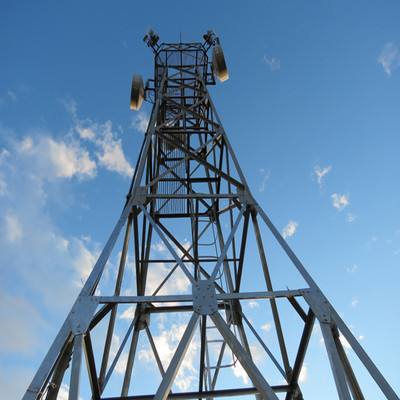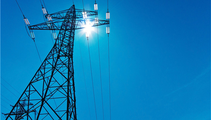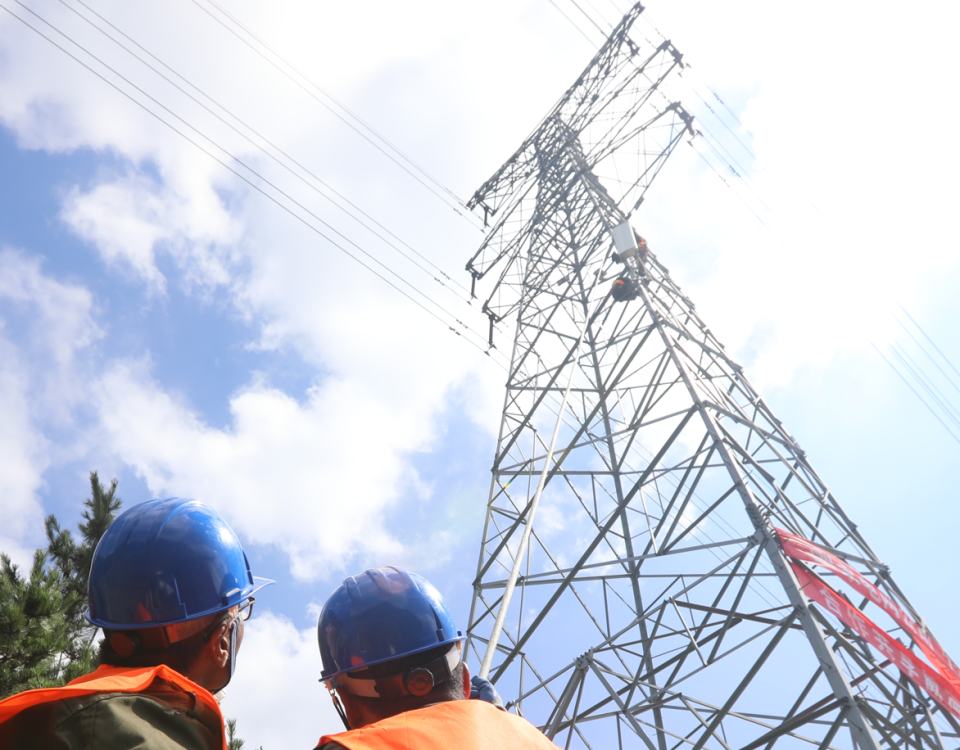
four legged angle iron /tube communication towers
January 12, 2019
Guidelines on Technical Specifications Communication tower
January 21, 2019Analysis of guyed steel lattice mast subjected to environmental loads
Analysis of guyed steel lattice mast subjected to environmental loads
Steel lattice masts rank among the most efficient load-bearing structures in the field of high-rise construction. The non-linear analysis of a guyed steel lattice mast is conducted using the SAP 2000 finite-element program for different ice thickness values at 1500 m of altitude. After definition of the geometrical model and cross- section properties, various load combinations are analysed. Finally, the wind speed- ice thickness relationship is obtained, and the maximum wind speed that the structure can withstand is determined for varying ice thicknesses.
- Introduction
Lattice mast is a general name for different kinds of steel masts.A lattice mast or truss mast is a freestanding framework mast. These structures can be used as transmission masts especially for
voltages of more than 100 kilovolts, as radio masts (self-radiating masts or carriers for aerials), or as observation masts for safety purposes. Big and heavy frame sections are not required in these
masts. This is why they are lighter than other mast types, and the modules can easily be connected to one another.
Steel lattice masts have been used for many years in the countries where the ice and wind loads are considerable. This is due to increasing demands of modern industry with regard to communication and energy. There are different styles of masts on which small wind generators are mounted: freestanding, guyed lattice, and tilt-up. Freestanding masts are relatively heavy duty, and they stay upright without the help of guy cables. Guyed lattice masts use guy cables to anchor the mast and keep it upright using a relatively small quantity of concrete. Cables stretch from three points near the top of the mast to the ground at some distance from the base of the mast. These constructions are quite light compared to freestanding masts, and therefore constitute the least expensive means for supporting a wind turbine. However, they require a larger area to accommodate the guy cables.
The technical efficiency and durability of steel lattice masts have increased in recent years. The behaviour of steel lattice masts has been investigated in literature. As the design procedure is significant in these masts, the structural analysis is related to the geometrical model and section properties. Thus, the module production and assembly steps, and economic costs, are directly related to the design of masts. Steel lattice masts on land are vulnerable structures. They are mostly affected by environmental loading. Wind loads are the most effective design criteria for these structures. However, the ice effect must also be taken into consideration, especially at high elevations. In cold regions, these two effects are combined. Therefore, the relationship between the wind and ice must be investigated by conducting proper finite-element analyses to avoid the collapse of such structures. In this paper, the non linear analysis of a guyed steel lattice mast 80 m in height is performed using the SAP 2000 program. While the model is constituted according to TS 648 load conditions are taken from TS 498. The altitude of the structure is taken to be 1500 m, and the snow region IV is adopted, which is the most conservative option. In this way, the analysis can also be used for other snow regions. The structure was first analysed without any ice effect. Afterwards, the ice thickness was gradually increased, and the relationship between the wind speed and ice thickness was determined.
- Materialand method
Proper sections and angles of the steel lattice mast are first determined. Afterwards, the three dimensional finite element model is given in Figure 1. Top view of the model is presented
in Figure 2. Face sections of the model, showing the distances with angles, are shown in Figure 3 and Figure 4.

Figure 1. 3-D model

Figure 2. Top view

Figure 3. A and B face sections

Figure 4. C face section
Table 1. Material properties
|
Material type |
Tensile strength [MPa] |
Yield strength [MPa] |
|
St52 (S355) |
510 |
360 |
Table 2. section properties
|
Member type |
Section type |
Size [mm] |
|
Column members |
Pipe |
48×7 |
|
Vertical members |
Circular |
16 |
|
Diagonal members |
Circular |
16 |
|
Guy members |
Circular |
16 |
Table 3 Wind speed and loads according to height
|
Height [m] |
Wind speed “v” [m/s] |
Wind load “q” 2 [kg/m ] |
|
0-8 |
28 |
50 |
|
8-20 |
36 |
80 |
|
20-80 |
46 |
130 |

A module 3015 mm in length is made of steel members. Columns are placed at an angle of 900 to the ground. Vertical steel members connect columns to one another, and are placed vertically with respect to the columns. Diagonal members are placed by definite angles to the columns, and they also connect the columns to one another. A column with diagonal and vertical members that constitute the module, are shown in Figure 5.

Figure 5. Module members
Guy members and modules are named according to the total height from the ground level. The guy and section numbers, with related heights, are presented in Figure 6.
Table 4. Height and snow properties
|
Altitude [m] |
Snow region |
Snow load qs 2 [kg/m ] |
|
1500 |
IV |
176 |
Table 5. Ice properties
|
Weight of unit volume [kN/mm³ ] |
|
7 |
There are 26 modules in the lattice mast. The column, vertical,and diagonal members in each face of the module are shownin Figure 7. Positive and negative wind directions affecting the
module are also presented in the figure.

Table 6 section properties
|
Member |
Section type |
Section size [mm] |
Section circumference [cm] |
Section area 2 [cm ] |
|
Column |
Pipe |
48×7 |
15.08 |
9.02 |
|
Vertical |
Circular |
16 |
5.03 |
2.01 |
|
Diagonal |
Circular |
16 |
5.03 |
2.01 |
|
Guy |
Circular |
16 |
5.03 |
2.01 |
|
Column |
Pipe |
48×7 |
15.08 |
9.02 |
|
Vertical |
Circular |
16 |
5.03 |
2.01 |
|
Diagonal |
Circular |
16 |
5.03 |
2.01 |
|
Guy |
Circular |
16 |
5.03 |
2.01 |
|
Column |
Pipe |
48×7 |
15.08 |
9.02 |
|
Vertical |
Circular |
16 |
5.03 |
2.01 |
|
Diagonal |
Circular |
16 |
5.03 |
2.01 |
|
Guy |
Circular |
16 |
5.03 |
2.01 |
|
Column |
Pipe |
48×7 |
15.08 |
9.02 |
|
Vertical |
Circular |
16 |
5.03 |
2.01 |
|
Diagonal |
Circular |
16 |
5.03 |
2.01 |
|
Guy |
Circular |
16 |
5.03 |
2.01 |
Load combinations used in the analysis are given in Eqn (1) and Eqn (2) as follows. The combinations are constituted by Snow loads, ice loads according to ice thickness values,
and wind loads effecting different heights of the lattice mast with wind speeds are given in Table 7.
|
Member |
Snow load 2 [kg/m ] |
Distributed snow load [kg/m] |
Ice thickness [mm] |
Distributed ice load [kg/m] |
Wind speed [km/h] |
Wind load according to height [kg/m] |
||
|
0-8 m |
8-20 m |
20-80 m |
||||||
|
Column |
176 |
– |
30 |
5.15 |
209 |
12.18 |
19.49 |
26.81 |
|
Vertical member |
4.42 |
3.03 |
4.06 |
6.50 |
8.94 |
|||
|
Diagonal member |
4.42 |
3.03 |
4.06 |
6.50 |
8.94 |
|||
|
Guy |
4.42 |
3.03 |
4.06 |
6.50 |
8.94 |
|||
|
Column |
176 |
– |
20 |
2.99 |
217 |
12.63 |
20.21 |
27.79 |
|
Vertical member |
4.42 |
1.58 |
4.21 |
6.74 |
9.26 |
|||
|
Diagonal member |
4.42 |
1.58 |
4.21 |
6.74 |
9.26 |
|||
|
Guy |
4.42 |
1.58 |
4.21 |
6.74 |
9.26 |
|||
|
Column |
176 |
– |
10 |
1.28 |
223 |
12.96 |
20.73 |
28.50 |
|
Vertical member |
4.42 |
0.57 |
4.32 |
6.91 |
9.50 |
|||
|
Diagonal member |
4.42 |
0.57 |
4.32 |
6.91 |
9.50 |
|||
|
Guy |
4.42 |
0.57 |
4.32 |
6.91 |
9.50 |
|||
|
Column |
176 |
– |
0 |
– |
226 |
13.14 |
21.03 |
28.92 |
|
Vertical member |
4.42 |
– |
4.38 |
7.01 |
9.64 |
|||
|
Diagonal member |
4.42 |
– |
4.38 |
7.01 |
9.64 |
|||
|
Guy |
4.42 |
– |
4.38 |
7.01 |
9.64 |
|||
load effects lateral members. Distributed snow load is calculated by considering top surface area of the members.


