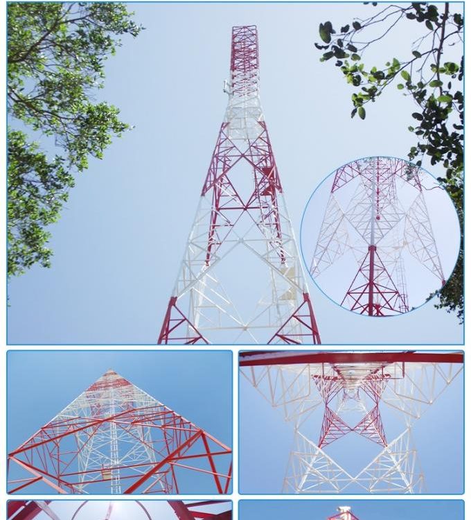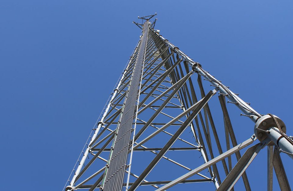
Difference Between Self-Supporting and Guyed Towers
July 7, 2024
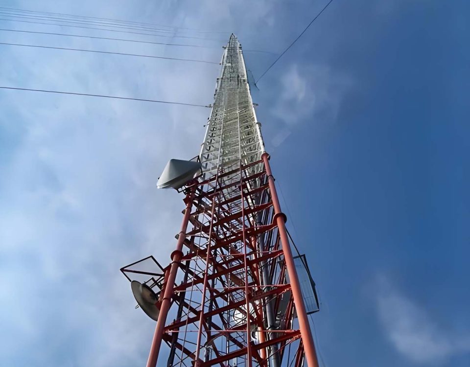
Guyed Wire Communication Tower
July 20, 2024GSM Communication Monopole Tower
Introduction
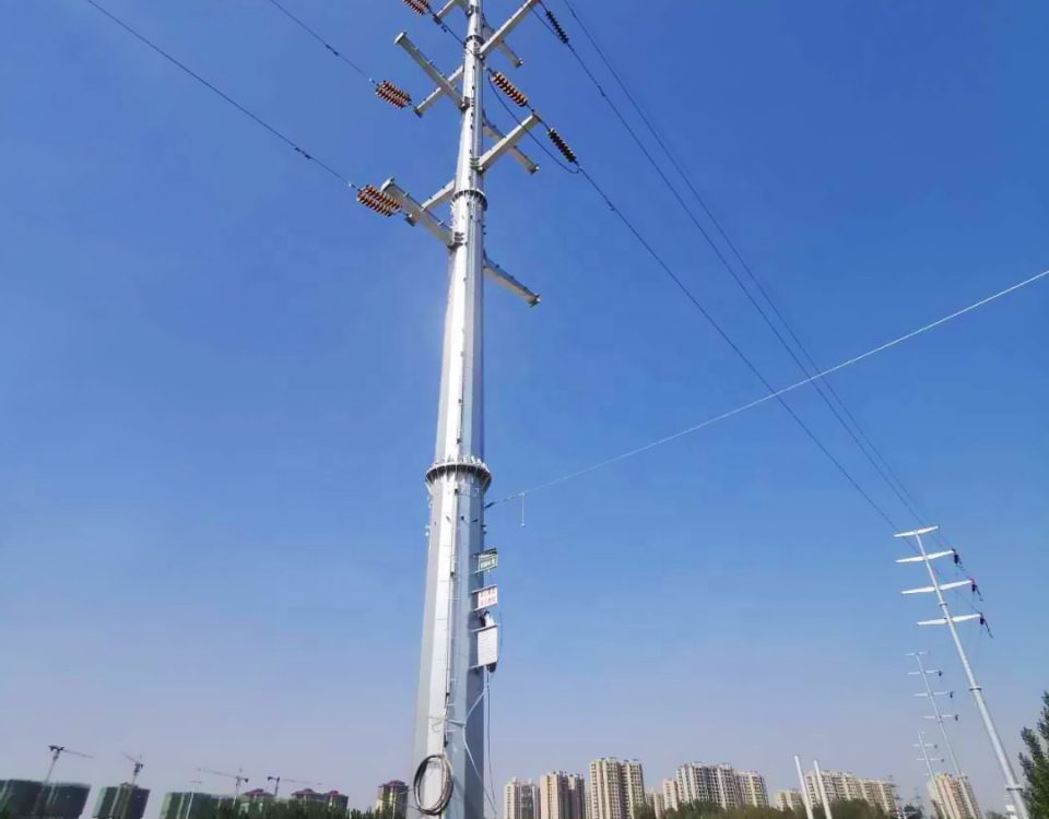
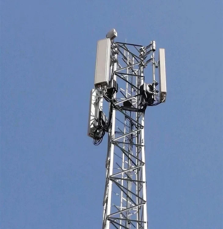
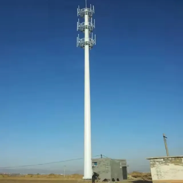
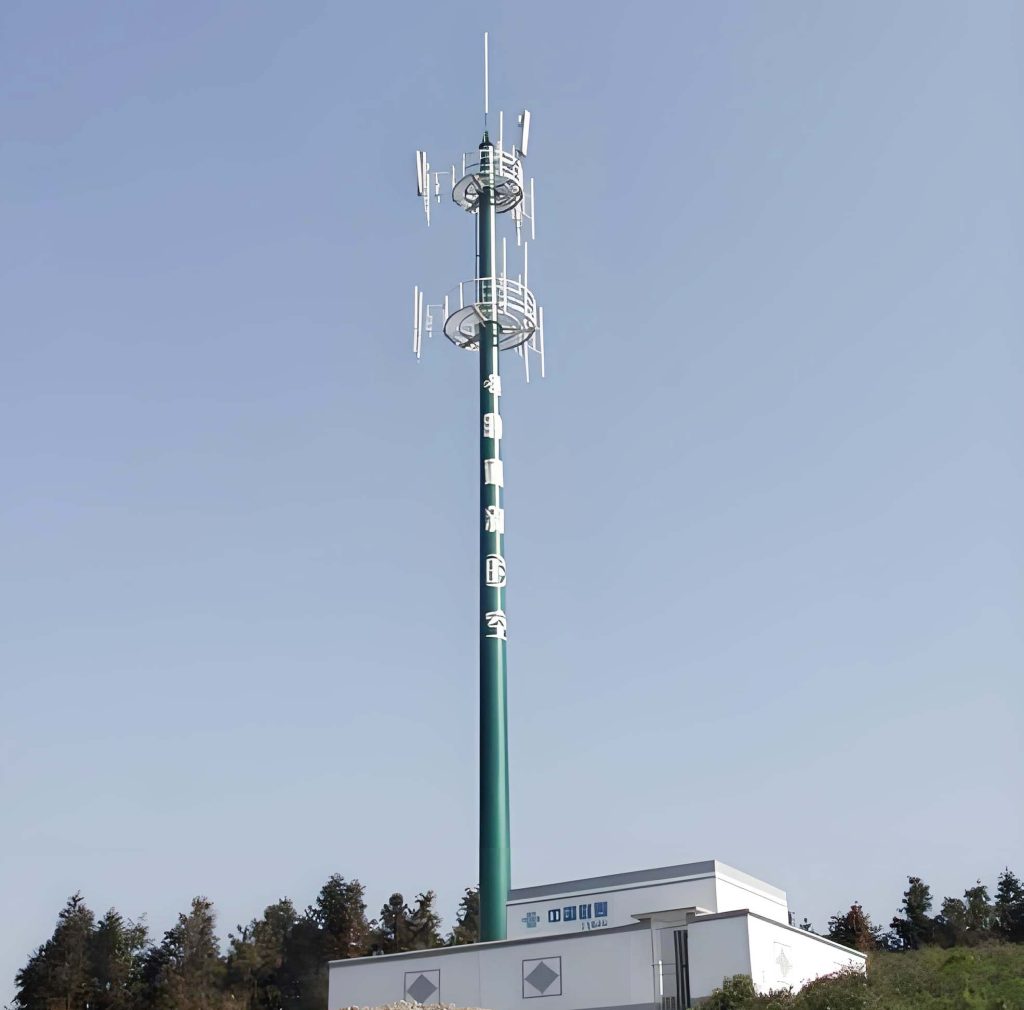
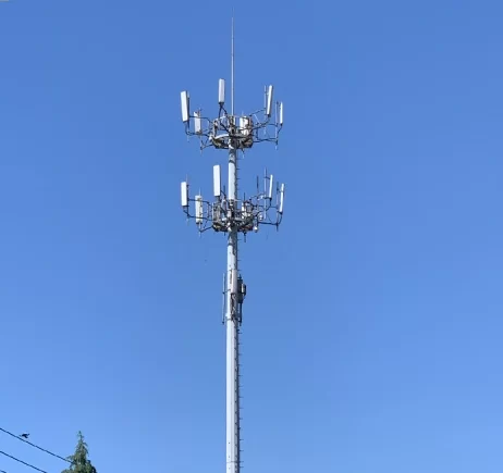
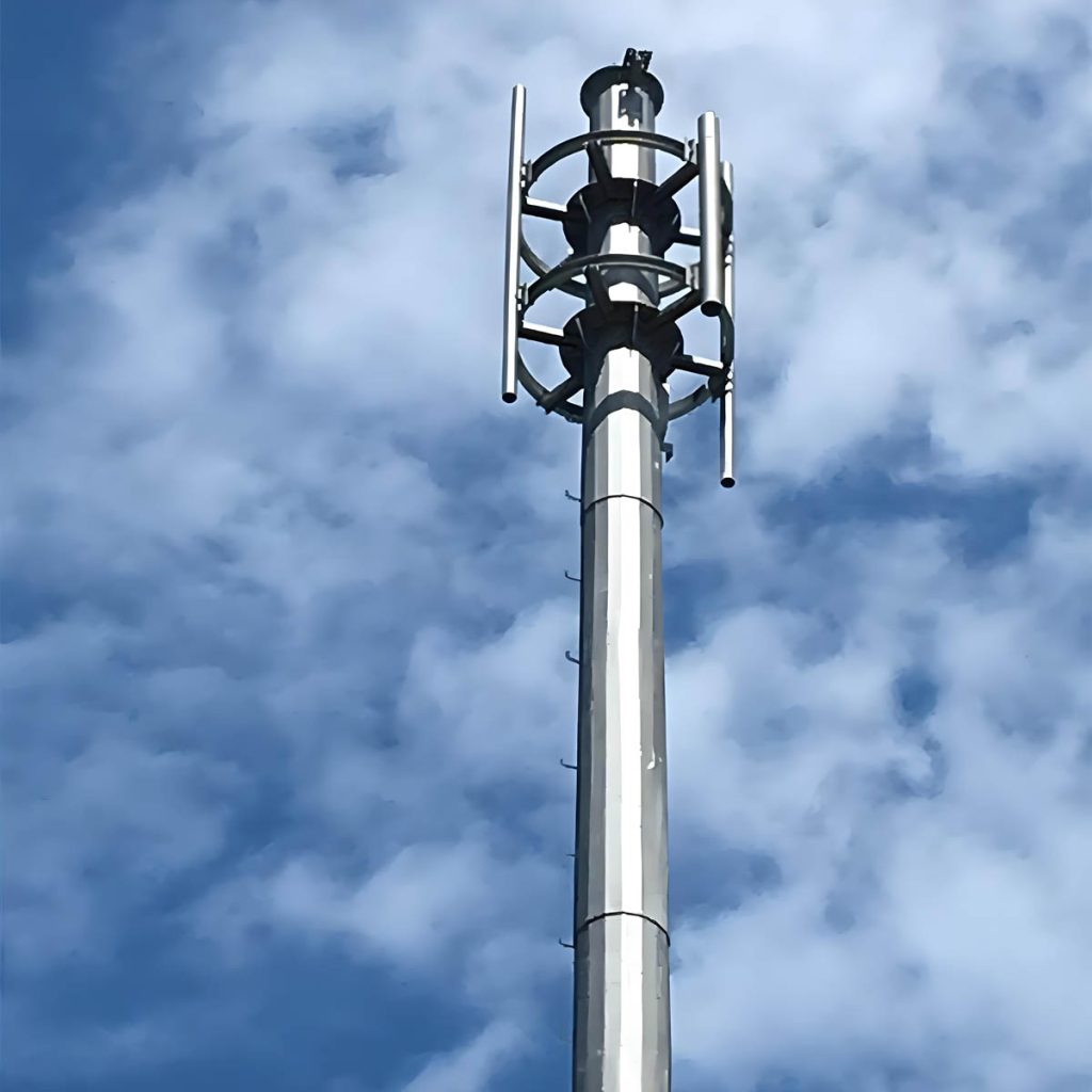
A GSM (Global System for Mobile Communications) monopole tower is a type of self-supporting structure used primarily for telecommunications. It is characterized by a single, tall, cylindrical pole that supports antennas and other communication equipment. Monopole towers are favored in urban and suburban settings where space is limited and aesthetic considerations are important. This detailed description covers the design, materials, parameters, construction, and maintenance of GSM monopole towers.
Structural Design
Monopole Structure
- Basic Structure:
- Monopoles are typically made from high-strength steel or aluminum.
- The pole is tapered, meaning it has a larger diameter at the base and gradually narrows towards the top.
- Sections of the pole are often flanged or slip-jointed for ease of assembly and transportation.
- Height and Diameter:
- Heights typically range from 15 to 60 meters (50 to 200 feet), depending on coverage requirements.
- The base diameter can range from 1 to 3 meters (3 to 10 feet), tapering to a smaller diameter at the top.
- Foundation:
- Foundations are designed to support the vertical load of the tower and the lateral loads imposed by wind and seismic activity.
- Common foundation types include reinforced concrete pads or pile foundations, depending on soil conditions.
Load Distribution
- Vertical Loads:
- The weight of the tower structure itself.
- The weight of antennas, mountings, and other equipment.
- The weight of ice or snow accumulation (in colder climates).
- Lateral Loads:
- Wind pressure is a significant lateral load, especially at greater heights.
- Seismic forces must be considered in earthquake-prone regions.
- Dynamic Loads:
- Vibrational loads from wind-induced oscillations.
- Loads due to the movement of maintenance personnel or equipment.
Design Considerations
- Wind Loading:
- Wind speed and pressure are calculated based on local meteorological data.
- The pole must resist wind loads without excessive deflection or vibration.
- Seismic Loading:
- Seismic design criteria are based on the seismic zone of the installation site.
- The foundation and pole are designed to withstand seismic forces without failure.
- Aesthetic Considerations:
- Monopoles are often designed to blend with their surroundings.
- Camouflaging techniques, such as faux tree designs or color matching, may be employed.
GSM Monopole Tower Specifications and Details
Monopole towers are essential for telecommunications, providing robust and reliable infrastructure for various applications. Below are the specifications for different series of standard towers, as well as details on their construction, durability, and maintenance.
Standard Tower Series
| Series | Height Range | Purpose |
|---|---|---|
| MP230 | 15-30 m | Telecommunication – designed for one operator |
| MP300 | 18-24 m | Telecommunication – designed for two operators |
| MP440 | 15-30 m | Telecommunication – designed for three operators |
| MP1500 | 30-48 m | Telecommunication – designed for four operators or 15 m² of windage for antennas |
Quick Details
- Tubular Steel Construction:
- Material: Monopoles are fabricated from domestic steel.
- Standards: Meet or exceed the latest EIA (Electronic Industries Alliance) criteria.
- Hot Dip Galvanization:
- Coating: Zinc coating on all hardware and components.
- Standards: Meets EIA and ASTM-A123 standards.
- Wind Force:
- Resistance: Designed to withstand winds of up to 105 mph.
- Customization: Monopoles requiring higher or lower wind or ice loads are custom engineered.
- Durable Construction:
- Applications: Meets heavy-duty industrial applications.
- Warranty: Comes with a five-year warranty on labor and materials.
- Tamper Resistant:
- Security Features: Climbing ladder anticlimb devices available.
- Access: Lockable access port prevents tampering.
- Protection: Coax, electrical power, and fiber optics are enclosed inside the structure to prevent vandalism.
- Ease of Maintenance:
- Access: Platforms are designed for ease of access to cameras, microwave equipment, and electronics.
- Safety: Climbing ladder is enclosed in a cage or can be equipped with an optional safety climb device.
- Numerous Applications:
- Security: Suitable for rail yard and intermodal facility security, high-security areas such as prisons, or defense installations.
- Border Security: Used by the U.S. Border Patrol for border security.
- Various Sizes, Heights, & Capacities:
- Customization: Contact us with the tower requirements, and we will provide a proposal for each specific tower need.
Summary Table
| Aspect | Details |
|---|---|
| Material | Domestic steel, hot-dip galvanized |
| Height Range (Series MP230) | 15-30 m |
| Height Range (Series MP300) | 18-24 m |
| Height Range (Series MP440) | 15-30 m |
| Height Range (Series MP1500) | 30-48 m |
| Wind Resistance | Up to 105 mph |
| Warranty | Five years on labor and materials |
| Security Features | Tamper-resistant, lockable access, enclosed wiring |
| Maintenance | Easy access platforms, optional safety climb device |
| Applications | Telecom, security, border patrol, high-security areas |
| Customization | Available for specific height, wind load, and capacity needs |
Materials
- Steel:
- High-strength, low-alloy (HSLA) steel is commonly used.
- Steel is often hot-dip galvanized to protect against corrosion.
- Yield strength typically ranges from 250 to 400 MPa (36,000 to 58,000 psi).
- Aluminum:
- Aluminum alloys are used for their lightweight and corrosion-resistant properties.
- Commonly used alloys include 6061 and 6063, which have good structural strength and corrosion resistance.
- Yield strength typically ranges from 150 to 275 MPa (22,000 to 40,000 psi).
- Concrete:
- Used for the foundation, typically reinforced with steel rebar.
- Compressive strength of concrete is usually around 25 to 40 MPa (3,600 to 5,800 psi).
- Fasteners and Connectors:
- High-strength bolts and nuts, often made from stainless steel or galvanized steel.
- Welds must be high-quality and inspected for defects.
Parameters and Specifications
| Parameter | Specification |
|---|---|
| Height | 15 to 60 meters (50 to 200 feet) |
| Base Diameter | 1 to 3 meters (3 to 10 feet) |
| Top Diameter | 0.3 to 1 meter (1 to 3 feet) |
| Material | High-strength steel or aluminum |
| Foundation Type | Reinforced concrete pad or pile foundation |
| Wind Speed Rating | Up to 160 km/h (100 mph) or higher, depending on location |
| Seismic Rating | Designed according to local seismic codes |
| Load Capacity | Varies, typically supports multiple antennas and equipment |
| Corrosion Protection | Hot-dip galvanization, painting, or anodizing (for aluminum) |
| Maintenance Interval | Annual inspections, with detailed structural assessments every 5 years |
Construction Process
- Site Preparation:
- Conduct a geotechnical survey to assess soil conditions.
- Clear the site and level the ground.
- Prepare access routes for construction equipment.
- Foundation Construction:
-
- Excavate the foundation area according to design specifications.
- Install reinforcement steel rebar.
- Pour concrete and allow it to cure properly.
-
- Pole Assembly and Erection:
- Transport pole sections to the site.
- Assemble the pole sections on the ground if space allows, or lift sections individually using cranes.
- Securely bolt or weld sections together according to engineering specifications.
- Antenna and Equipment Installation:
- Install mounting brackets and antennas.
- Run cabling and connect to power and communication systems.
- Final Inspection and Testing:
- Inspect the entire structure for alignment, connections, and integrity.
- Perform load tests to ensure stability under design loads.
- Conduct electrical and communication tests to verify functionality.
Maintenance Requirements
- Regular Inspections:
- Visual inspections every 6 to 12 months to check for signs of corrosion, wear, or damage.
- Detailed structural inspections every 5 years, including ultrasonic testing of welds and bolts.
- Corrosion Protection Maintenance:
- Reapply protective coatings as necessary.
- Touch up any damaged areas promptly to prevent corrosion.
- Equipment Maintenance:
- Regularly check and maintain antennas, cables, and other installed equipment.
- Ensure all connections are secure and free from corrosion.
Applications
- Urban and Suburban Telecommunications:
- Provide cellular coverage in densely populated areas.
- Often installed on building rooftops or in small plots of land.
- Rural Telecommunications:
- Used in rural areas where space is available and aesthetic concerns are minimal.
- Provide coverage over larger areas due to their height.
- Specialized Installations:
- Used in areas with specific aesthetic requirements, such as parks or historical districts.
- Camouflaged designs to blend with the environment.
Summary Table
| Aspect | Details |
|---|---|
| Primary Use | GSM mobile communications |
| Typical Height | 15 to 60 meters (50 to 200 feet) |
| Material | High-strength steel or aluminum, galvanized for corrosion resistance |
| Foundation | Reinforced concrete pad or pile foundation |
| Wind Load Capacity | Designed for local wind speeds, typically up to 160 km/h (100 mph) |
| Seismic Design | Built to withstand seismic forces according to local codes |
| Construction Time | 2 to 6 months, depending on height and complexity |
| Maintenance | Annual visual inspections, detailed inspections every 5 years |
| Aesthetic Options | Camouflaging techniques, such as faux trees or color matching |
| Load Capacity | Supports multiple antennas and communication equipment |
This detailed description provides a comprehensive understanding of GSM communication monopole towers, including their design, materials, construction process, and maintenance. These towers play a crucial role in modern telecommunications infrastructure, enabling reliable mobile communication services across various environments.
Case Study: GSM Monopole Tower Installation
To further illustrate the detailed process and considerations involved in the installation of a GSM monopole tower, we will explore a hypothetical case study of a 40-meter (131 feet) monopole tower installation in a suburban area.
Site Selection and Survey
- Site Selection:
- The site is chosen based on coverage requirements and accessibility.
- Proximity to existing infrastructure, such as power supply and communication networks, is considered.
- Geotechnical Survey:
- Soil testing is conducted to determine the soil type, bearing capacity, and groundwater level.
- This information is used to design the foundation appropriately.
- Environmental Impact Assessment:
- An environmental impact assessment (EIA) is performed to evaluate potential impacts on the local environment and community.
- Mitigation measures are planned to minimize disruption during construction.
Design Phase
- Structural Design:
- A detailed structural analysis is conducted using software tools to ensure the monopole can withstand all expected loads.
- The tapering design, material selection, and section lengths are finalized.
- Foundation Design:
- Based on the geotechnical survey, a reinforced concrete pad foundation is chosen.
- The foundation dimensions are calculated to ensure adequate support and stability.
- Antenna and Equipment Layout:
- The layout of antennas and other equipment is planned to optimize coverage and minimize interference.
- Mounting brackets and cable management systems are designed.
Materials Specification
- Steel Monopole Sections:
- Made from high-strength, low-alloy steel with a yield strength of 350 MPa (50,000 psi).
- Sections are hot-dip galvanized to a thickness of 85 microns for corrosion protection.
- Concrete Foundation:
- Foundation concrete has a compressive strength of 30 MPa (4,350 psi).
- Reinforced with steel rebar to enhance tensile strength and durability.
- Fasteners and Connectors:
- High-strength bolts (Grade 8.8) are used for section connections.
- Stainless steel or galvanized steel nuts and washers ensure long-term reliability.
Construction Process
- Preparation:
- The site is cleared, and temporary access roads are built.
- Construction equipment and materials are transported to the site.
- Foundation Construction:
- The foundation area is excavated according to design specifications.
- Steel rebar is installed, and formwork is set up.
- Concrete is poured and allowed to cure for at least 28 days to achieve full strength.
- Monopole Assembly:
- The monopole sections are delivered to the site and laid out for assembly.
- Sections are lifted using cranes and bolted or welded together as per the design.
- Each connection is inspected for alignment and tightness.
- Antenna Installation:
- Antennas and mounting brackets are installed at the designated heights.
- Cables are run from the antennas to the base station equipment, ensuring proper routing and securing.
- Final Inspection and Testing:
- The entire structure is inspected for compliance with design specifications.
- Load testing is performed to verify structural integrity.
- Electrical and communication systems are tested to ensure proper functionality.
Maintenance Plan
- Annual Inspections:
- Visual inspections to check for signs of corrosion, wear, and structural integrity.
- Inspection of antennas and equipment to ensure they are securely mounted and operational.
- Detailed Structural Inspections:
- Every 5 years, a more thorough inspection is conducted, including non-destructive testing (NDT) of welds and bolts.
- Ultrasonic testing, magnetic particle testing, and radiographic testing may be used to detect internal defects.
- Corrosion Protection Maintenance:
- Reapply protective coatings as necessary, especially in areas showing signs of wear or damage.
- Regular cleaning and inspection of galvanized surfaces to remove any contaminants.
- Equipment Maintenance:
- Routine checks and maintenance of antennas, cables, and connectors.
- Ensuring all electrical components are functioning correctly and safely.
Challenges and Solutions
- Wind Load Considerations:
- In areas with high wind speeds, additional design measures such as increased pole diameter or stronger materials may be required.
- Dynamic dampers can be installed to reduce wind-induced vibrations.
- Seismic Considerations:
- In seismic zones, the foundation design must account for potential ground movement.
- Flexible connections and base isolators can help absorb seismic energy and protect the structure.
- Aesthetic Integration:
- In suburban or urban areas, monopoles can be designed to blend with surroundings, using camouflage techniques such as faux trees or customized paint schemes.
- Community consultations can help address aesthetic concerns and gain public support.
Summary Table of Case Study
| Aspect | Details |
|---|---|
| Location | Suburban area |
| Height | 40 meters (131 feet) |
| Base Diameter | 2.5 meters (8.2 feet) |
| Top Diameter | 0.5 meters (1.6 feet) |
| Material | High-strength, low-alloy steel, hot-dip galvanized |
| Foundation Type | Reinforced concrete pad |
| Wind Speed Rating | Designed for up to 160 km/h (100 mph) |
| Seismic Rating | Designed according to local seismic codes |
| Construction Duration | 4 months |
| Aesthetic Considerations | Faux tree design to blend with surroundings |
| Load Capacity | Supports multiple antennas and communication equipment |
| Maintenance Interval | Annual inspections, detailed inspections every 5 years |
GSM communication monopole towers are vital components of modern telecommunications infrastructure, providing reliable connectivity in various environments. Their design and construction require careful consideration of numerous factors, including structural integrity, material selection, environmental impact, and maintenance requirements. By adhering to rigorous design standards and best practices, monopole towers can deliver efficient and long-lasting service, ensuring robust mobile communication networks.
This comprehensive analysis and case study illustrate the detailed process and scientific principles behind the design, construction, and maintenance of GSM monopole towers, highlighting their importance in supporting global communication networks.


