
Structural Types of Towers and Their Impacts
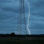
Lightning Protection Angle Tower
March 2, 2025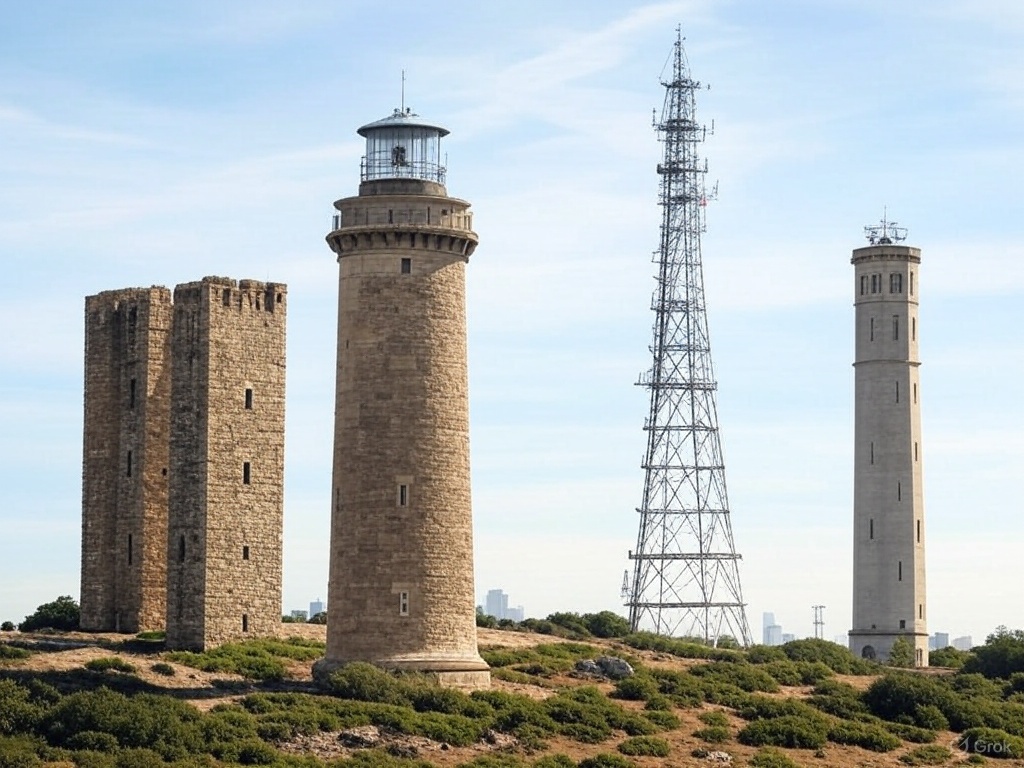
a. Self-Supporting Towers (Lattice/Monopole)
Self-supporting towers, including lattice and monopole designs, are widely used for their stability and adaptability.
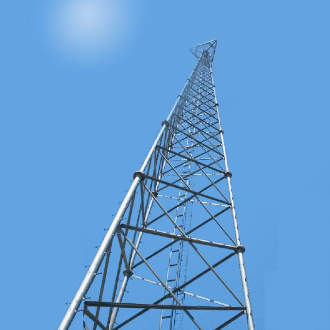
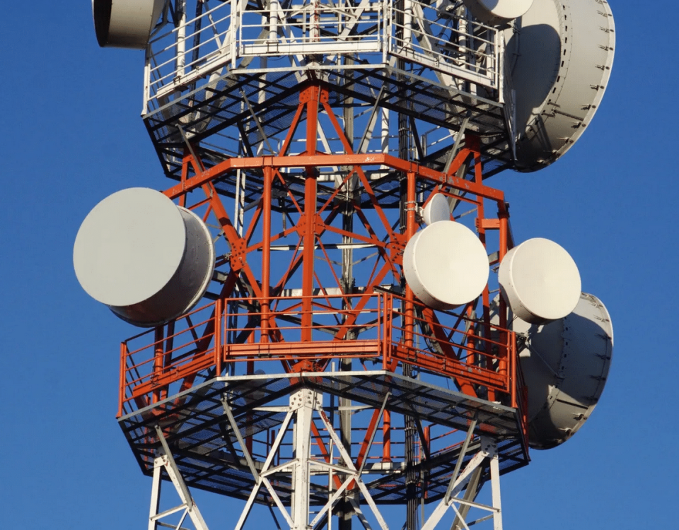
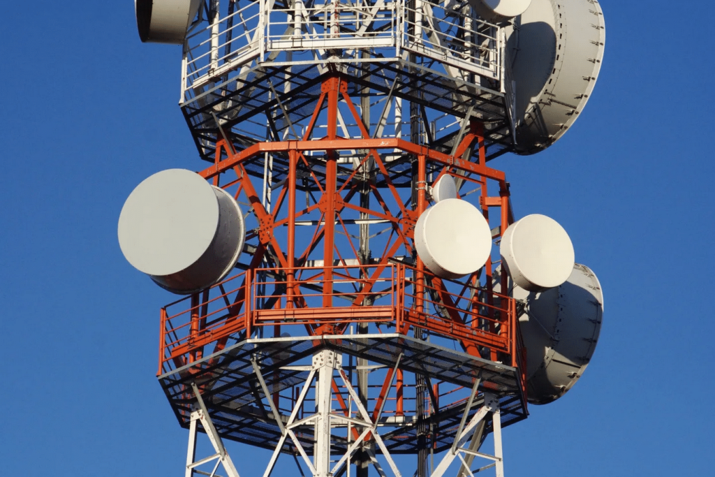
- Lattice Towers: Characterized by triangular or square cross-sections, these towers provide high rigidity and load-bearing capacity, ideal for mounting multiple antennas . Their wide base reduces sway, ensuring consistent antenna alignment and radiation patterns. However, their bulky structure may increase wind load stress, potentially altering antenna sidelobe levels .
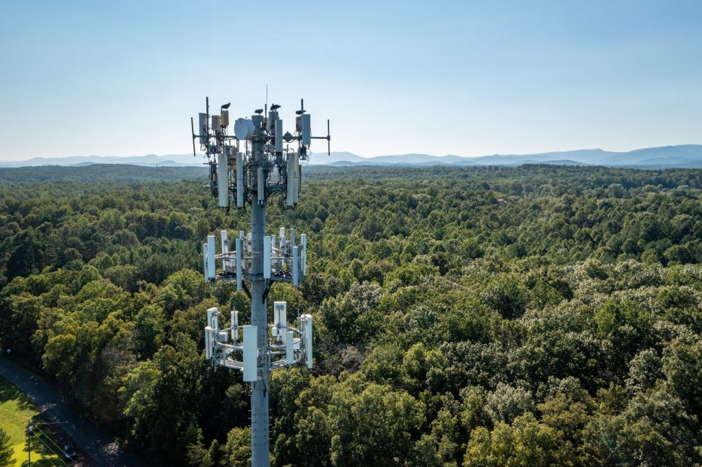
- Monopole Towers: Single-pole structures like tubular or tapered monopoles are space-efficient and aesthetically suitable for urban areas. While their compact design minimizes visual intrusion, limited mounting space can restrict antenna placement, affecting directional coverage and gain optimization .
b. Guyed Towers
Guyed towers rely on tensioned cables for stability, enabling taller heights at lower material costs. However:
- Sway and Oscillation: Guy wires introduce susceptibility to wind-induced oscillations, which may destabilize antenna alignment. This can degrade signal consistency, especially for high-frequency bands (e.g., 5G mmWave) requiring precise line-of-sight .
- Electromagnetic Interference (EMI): Steel guy wires may act as parasitic conductors, introducing EMI that distorts antenna radiation patterns or increases noise .
c. Roof-Mounted Towers
Roof-mounted structures (e.g., masts or frameworks) face unique challenges:
- Height Limitations: Restricted by building height, antennas may suffer reduced coverage radius. For example, a 30m roof tower typically covers 1–3 km, while a 40m+ tower extends to 5 km .
- Structural Load and Vibration: Building resonance and thermal expansion/contraction can shift antenna positions, altering radiation efficiency and polarization purity .
2. Tower Height and Antenna Performance
Tower height directly correlates with signal propagation and coverage:
- Coverage Radius: Higher towers extend the radio horizon, overcoming Earth’s curvature. A 305m tower achieves ~40 km line-of-sight, while a 3,000m balloon-mounted antenna extends to 200 km . However, excessive height introduces path loss trade-offs and signal delay due to increased reflecting surfaces (e.g., terrain or buildings) .
- Gain and Directionality: Elevated antennas reduce ground reflections and multipath interference, enhancing gain. For instance, increasing elevation from 0° to 60° improves signal quality by 9.1 dB at UHF frequencies .
3. Material Properties and Dielectric Effects
Tower materials influence antenna efficiency through conductivity and dielectric losses:
- Conductive Materials: Copper and aluminum minimize resistive losses (skin effect), critical for high-frequency antennas. Iron or steel, despite higher strength, increase ohmic losses, reducing radiation efficiency by up to 2.65 dB in low-impedance arrays .
- Dielectric Substrates: Towers with composite materials (e.g., fiberglass radomes) must balance dielectric constant (ε) and loss tangent (tanδ). High ε materials shrink antenna size but raise moisture-induced losses, while low ε substrates (e.g., Rogers® laminates) optimize bandwidth and gain .
4. Environmental and Mechanical Stressors
a. Wind Load
Wind exerts torsional (K-factor) and lateral forces on towers:
- Structural Resonance: Antennas act as sails, amplifying wind load. For example, a 30 mph wind generates sufficient inertia to collapse poorly braced lattice sections .
- Radiation Pattern Distortion: Swaying antennas disrupt beamforming accuracy, increasing sidelobe levels and reducing directivity .
b. Temperature Variations
Thermal expansion/contraction alters tower geometry:
- Material Fatigue: Repeated thermal cycling weakens joints, causing misalignment. Steel towers expand ~1.2 mm per 10°C per 100m, potentially shifting antenna azimuth .
- Dielectric Property Shifts: Temperature fluctuations change substrate ε and tanδ, detuning resonant antennas and narrowing bandwidth .
5. Case Studies and Design Standards
Research highlights the interplay between tower design and antenna performance:
- TIA-222 Standards: Comparative studies show lattice towers designed under TIA-222-G withstand 15% higher wind loads than TIA-222-H-compliant structures, ensuring stable radiation patterns under extreme conditions .
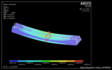
- Strengthening Techniques: Component-level reinforcement (e.g., angle-section bracing) reduces displacement by 20% in retrofitted towers, improving antenna mounting stability .
6. Optimization Strategies
To mitigate adverse effects:
- Aerodynamic Design: Streamlined monopoles or shrouded lattice sections reduce wind load by 30% .
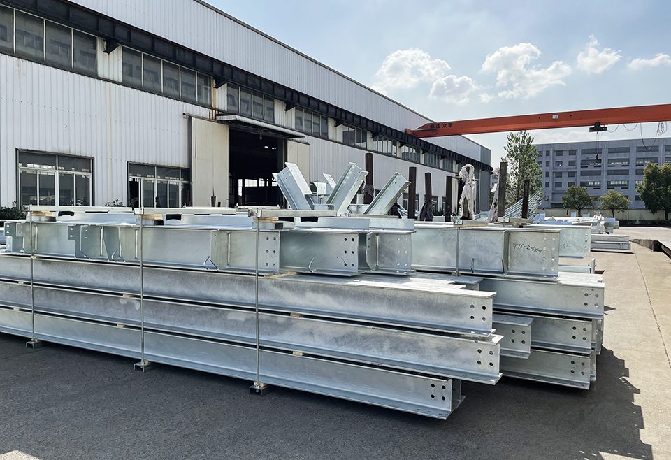
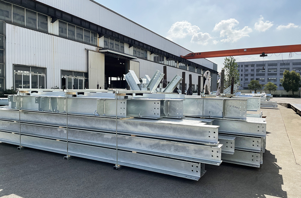
- Material Selection: High-strength, low-loss alloys (e.g., galvanized steel) balance durability and conductivity .
- Dynamic Dampers: Tuned mass dampers suppress tower oscillations, maintaining antenna alignment within ±0.5° during storms .
Conclusion
Tower structures profoundly influence antenna performance through mechanical stability, material properties, and environmental resilience. Optimal design requires balancing structural robustness with electromagnetic efficiency, guided by standards like TIA-222 and case-specific simulations. Future trends, such as drone-mounted towers , may further decouple height limitations from structural constraints, revolutionizing wireless communication architectures.
Related posts
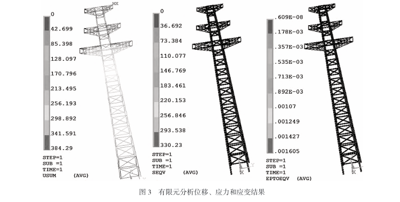
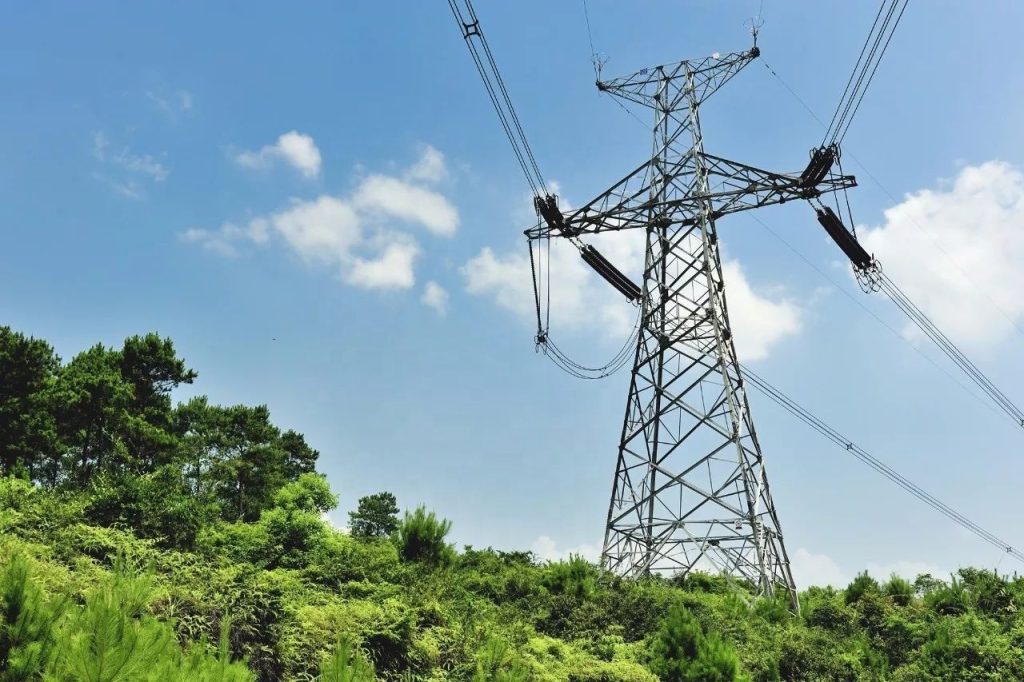
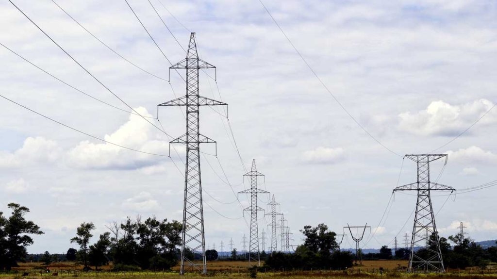
The analysis of the bearing capacity of a power transmission line steel tower highlights the complexity and importance of structural and foundation design. By understanding the interplay of loads, material properties, and environmental factors, engineers can optimize tower performance and ensure reliability in power networks. Tables and case studies further illustrate best practices and design considerations.
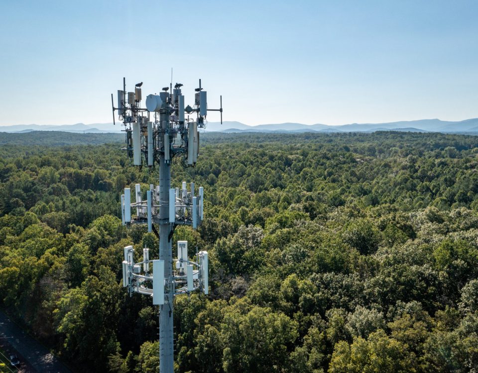
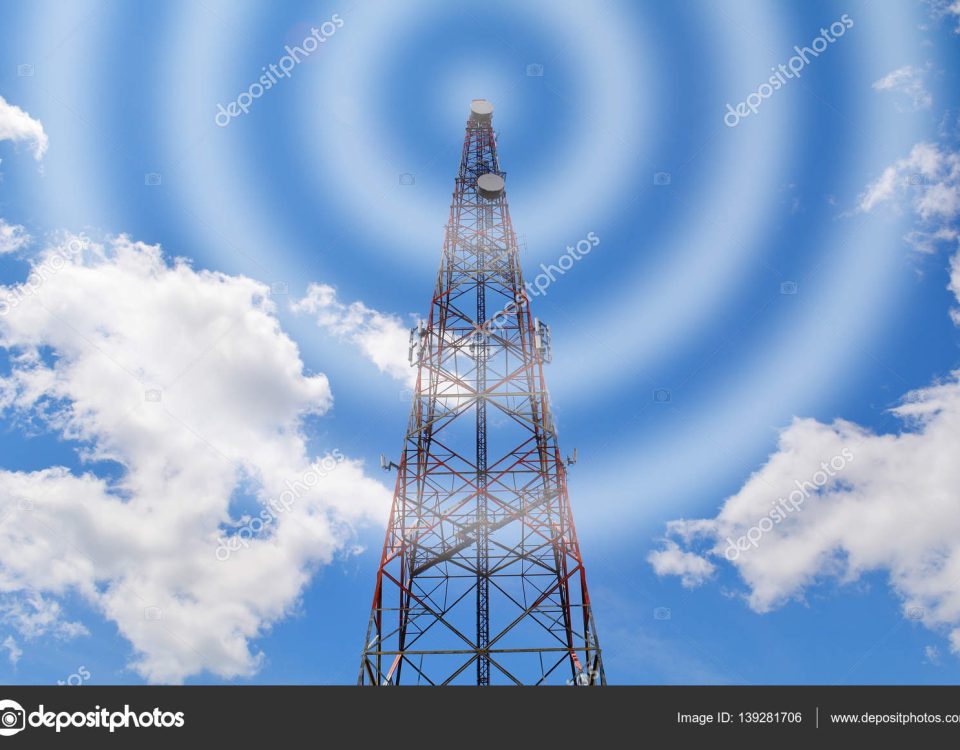
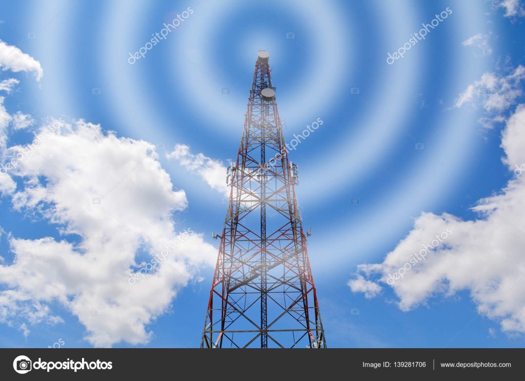
A communication tower is a type of signal transmission tower, also known as a signal transmission tower or communication iron tower. In the construction of modern communication and radio and television signal transmission towers, regardless of whether users choose ground level or rooftop iron towers, they all play a role in raising communication antennas, increasing the service radius of communication or television transmission signals, and achieving ideal specialized communication effects. In addition, the rooftop also plays a dual role in lightning protection grounding, route warning, and decoration of office buildings.