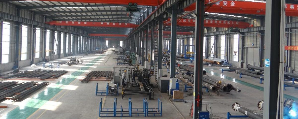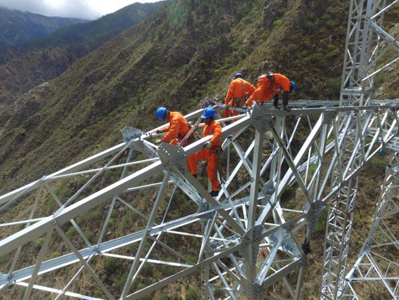
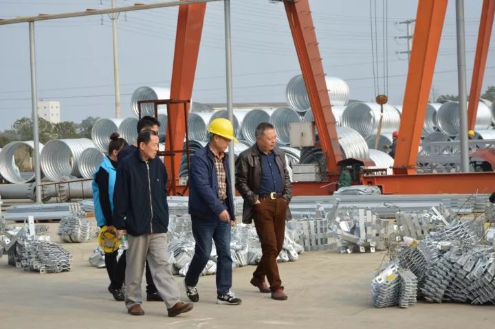
Components & Parts Inspect : Bolivia 230KV Angle Steel Tower Project
April 8, 2018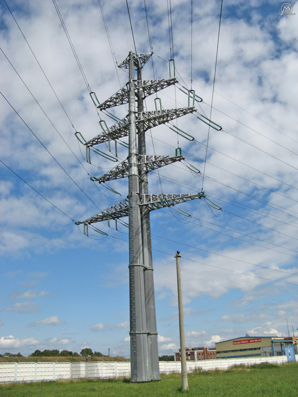
Galvanized Steel Electrical Power Pole for Transmission Line – HDG Polygonal Shape
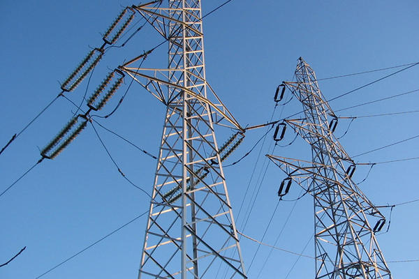
April 11, 2018Electric Transmission Line galvanized Steel Lattice Tower Accessories
Electrical Tower Accessories
a) General
Each tower shall be provided with the necessary pull-off plates, U-bolts, strain links, etc., at all conductor and shield wires attachment points.
b) Step Bolts
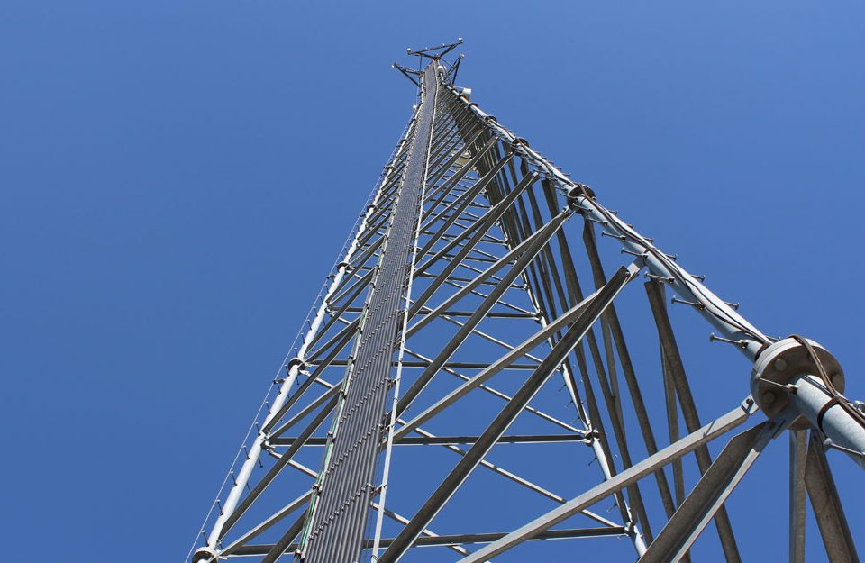
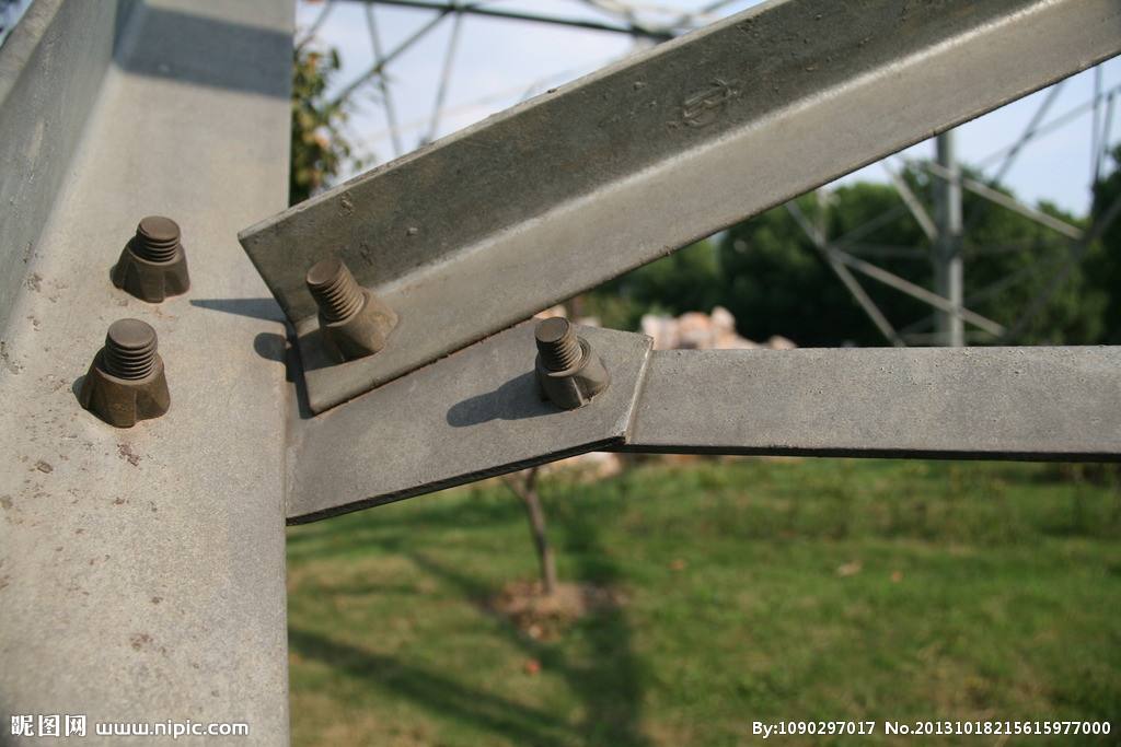
For single circuit type towers step bolts shall be provided on one tower leg. They shall begin directly above the foundation and continue to the tower top. They shall be spaced at a distance of 330 mm from center to center, distributed strictly alternating on the outer sides of the leg angles. The spacing distance of all step bolts shall be equal on the entire tower. Spacing tolerances according to VDE 0210/12.85 shall be accepted. Only the step bolts above the anti climbing device shall be installed permanently on the tower. Bolts below the anti climbing device shall either be installed, or be delivered to Employer’s store, at Employer’s discretion.
All step bolts shall have a free tread width of 20 cm. For protection against slipping a lateral limit of min. 20 mm above top of step shall be provided. The tread side of the step bolts shall be uniform for all towers. The fastening side may accommodate different sizes, to take advantage of holes provided for structural bolts. Step bolts shall be rated at least for a concentrated load of 1500 N, acting vertically at the most unfavorable position. If applied in place of a structural bolt, its loading has to be considered, too.
c) Signs
Towers shall be provided with all the steelworks necessary for mounting of signs.
Weather resisting enamelled plates shall be supplied as danger signs and installed on all towers. The plates shall depict, in black, skull and crossbones. The word DANGER shall be boldly written in red both in Amharic and English languages. On the same plate, tower numbers in black and phase designations in yellow for R-phase, in green for S-phase and in violet for T-phase shall be shown. The phase designations shall be marked black with hour numbers (R0, S4 and T8).
Aerial visible plates shall be yellow script at least 370 mm high on a black background and shall specify the tower number. They shall be fitted in an approved position on the transverse face of tower for every tension and every fifth suspension towers.
Tower circuit colour plates shall be 305 mm deep and 100 mm long.
Signs shall normally be on the transverse face of a tower with the exception of towers located within 40 meters of roads in which case the signs shall be affixed facing the highway. The mounting height shall be approximately 3 meters above ground level. Mountings shall be made of galvanized transmission line bolts, nuts and washers.
All plates shall be of adequate thickness to ensure no bending of plates can take place and no cracking of surface coloring can occur.
Damaged, chipped or cracked plates and surface coloring will not be accepted.
d) Conductor and Earth wire Attachments
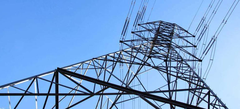
Conductor and earth wire attachments shall be considered as part of the respective basic towers and shall be supplied as integral parts of them.
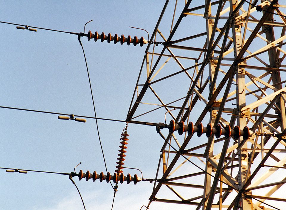
All conductor suspension points shall provide 3 brackets for installation of suspension hinges suitable for the attachment of double and single insulator strings associated with suspension conductor support assemblies. Both, individual hinges and suspension point assemblies shall be orientated in line direction, allowing the insulator strings to swing in cross-arm direction.
Tension towers shall have brackets suitable for the attachment of tension hinges for double insulator strings associated with dead-end conductor assemblies.
The spacing of all double strings shall satisfy the requirements as per Article “Insulator Strings” below. Insulators of double strings shall be kept parallel at all line angles.
The Earth wire/OPGW shall be connected to the suspension tower peaks by hinge(s) orientated in line direction, allowing the suspension assembly to swing in cross-arm direction. Connection to tension towers shall be provided by tension assemblies, to be fixed to the tower peak.
For direct connection of overhead shield wire shunts to the towers, 2 sets of two holes, each, shall be provided on every earth wire peak.
Additional maintenance bracket on suspension cross-arms and additional inner and outer tension points at each tension cross-arm shall be provided fur use during stringing and maintenance operations. On tension cross-arms spare holes are to be provided so that in combination with swivel bolts or shackles they provide mountings for stringing pulleys.
All towers shall have provisions for the attachment of both single and double insulator strings. Dead-end towers with one Earth wire/OPGW shall have brackets suitable for twin earth wire attachments to substation gantries. The additional earth-wire connection is to be provided by the contractor between the terminal tower and the substation gantry. Double insulator strings shall be fixed with two points on the cross-arms to provide maximum security in case of rupture of one insulator string.
e) Tower Grounding and Earth Clamping Bolts
For connecting additional grounding devices, sets of two holes each, are to be provided in all four stub angles to take two 16 mm bolts.
As service earthing point, one earthing bolt M 16, DIN 48088 part 2, to be delivered with spring washer, flat washer and nut shall be installed on the cross-arm steelworks, near to the base side of every insulator string in an easily accessible location, subject to the Engineer’s approval. This earthing point will be required for system earthing during line repair and maintenance work. The earth clamping bolt shall be designed to withstand a current of 30 kA for a period of 1 second.
f) Solar Powered Aviation Hazard Lighting
Each tower shall be equipped with suitable means for possible installation of solar powered aviation hazard lights.
Fixing holes shall be provided, on both top cross-arms, permitting installation of two solar panels with a total size of min. 1,2 m x 1,2 m, at an inclination of 45º to the horizontal, facing due south. The fixing points shall be versatile, to account for different tower orientations and be designed to safely transfer the full wind load acting on the panels.
In the tower shaft, at top cross-arm level, a steel grating work platform of min. 2 m² shall be provided, suitable for installation of a battery/control unit enclosure with dimensions of min. B x D x H of 80 cm x 80 cm x 100 cm, and a weight of min. 100 kg. Besides the box, the platform shall be able to carry, simultaneously, the weight of 3 linesmen with tackle.
At the earth wire peak, two holes shall be provided, for vertical attachment of a warning light assembly.
Above facilities are considered integral tower parts and shall be provided, regardless whether the scope of work actually requires supply of warning lights.
g) Stubs and Setting Templates
Each tower shall be provided with the foundation stubs, which shall have a section size, which is not less than the tower leg. Sufficient stub setting templates shall be provided to allow unhindered foundation installation and shall cover the full range of tower types, leg and body extensions.
h) Anti-Climbing Device
Each tower shall be fitted with an anti climbing device to prevent unauthorized persons from climbing the tower. The anti climbing device shall be of a type as shown in the Bid Drawings, and shall be fixed at a height of approximately 6 meters above the foundation.
A sideward opening gate of an approved design shall be fitted in the anti-climbing device of the step leg of the tower and provisions made for locking the gate with a bolt, nut and locknut.
i) Bird Guards
Tower members positioned above insulator strings/solar panels (if applicable) shall be fitted with stainless steel needle strips, effectively preventing birds from sitting in these locations. The strips shall extend sufficiently, horizontally beyond the protected location and be applied to all surfaces a bird can sit on. Where needles are projecting from the cross-arm contour towards live parts, the tower clearance diagram shall consider the height of the needles.

