Self-Guying Portable Mobile Antenna Steel Towers
December 18, 2024
Galvanized Steel Transmission Line Pole
January 5, 2025Analysis of the Bearing Capacity of Power Transmission Line Steel Tower
The analysis of the bearing capacity of a power transmission line steel tower highlights the complexity and importance of structural and foundation design. By understanding the interplay of loads, material properties, and environmental factors, engineers can optimize tower performance and ensure reliability in power networks. Tables and case studies further illustrate best practices and design considerations.
Analysis of the Bearing Capacity of a Power Transmission Line Steel Tower
The bearing capacity of power transmission line steel towers is critical for ensuring structural stability and reliable electricity transmission. This article delves deep into the structural behavior, influencing factors, and methodologies for analyzing the bearing capacity of these steel towers. We will also examine design considerations, material properties, and various failure modes. The study incorporates theoretical principles, practical insights, and cutting-edge techniques to optimize tower performance and safety.
Introduction
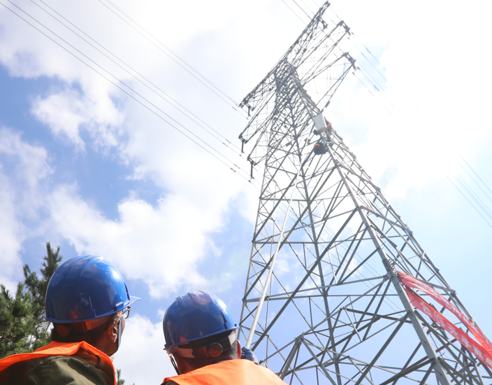
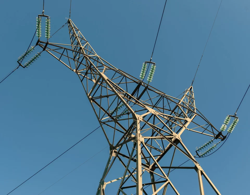
Steel towers are a vital component of power transmission infrastructure, supporting overhead lines that transfer electricity across vast distances. Their structural stability is of paramount importance, especially given the increasing demands of modern energy systems. A tower’s bearing capacity refers to its ability to safely support and transfer loads, including wind, ice, conductor weight, and other environmental forces.
This article offers a comprehensive analysis of the bearing capacity of steel towers used in power transmission lines. It explores design principles, failure modes, and modern techniques for improving performance. Engineers, designers, and researchers will find valuable insights to help optimize the efficiency and safety of transmission line infrastructure.
Understanding Bearing Capacity in Steel Towers
What is Bearing Capacity?
Bearing capacity in steel towers refers to the ability of the structure to withstand applied loads without undergoing excessive deformation, instability, or failure. The term encompasses both the ultimate capacity (maximum load before failure) and serviceability limit states (acceptable performance under normal conditions).
Significance of Bearing Capacity in Power Transmission Lines
Steel towers must handle complex loads, including:
- Vertical Loads: Self-weight of the tower, conductors, and insulators.
- Horizontal Loads: Wind pressure and dynamic forces.
- Environmental Loads: Ice accumulation and seismic forces.
An inadequate bearing capacity can lead to catastrophic failure, disrupting power supply and causing financial losses.
Static and Dynamic Load Analysis
Static Load Analysis
Static loads remain constant over time and include the tower’s weight and permanent conductor tension. The analysis ensures the structure can carry these loads without yielding or collapsing.
| Load Type | Magnitude Range | Calculation Method |
|---|---|---|
| Dead Load | 10–20 kN/m | Material density × volume |
| Conductor Tension | 5–15 kN | Based on conductor weight |
Dynamic Load Analysis
Dynamic loads are time-dependent and can result from wind gusts, earthquakes, or operational vibrations. They are evaluated using modal analysis and time-history response techniques.
| Dynamic Load Type | Effect on Structure | Mitigation Measures |
|---|---|---|
| Wind Gusts | Sway and oscillation | Aerodynamic tower designs |
| Earthquakes | Base shear and resonance | Seismic dampers, reinforced foundations |
Bearing Capacity Estimation
Foundation Considerations
The foundation plays a crucial role in transferring loads from the tower to the ground. Bearing capacity depends on soil properties and foundation type.
| Soil Type | Bearing Capacity (kPa) | Preferred Foundation |
|---|---|---|
| Clay | 100–200 | Pad foundation |
| Sand | 200–300 | Pile foundation |
| Rock | >500 | Rock anchor foundation |
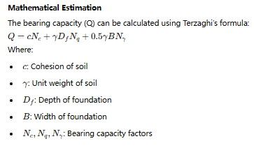
Mathematical Estimation
Failure Mechanisms
Buckling of Members
Buckling occurs in tower legs or braces when compressive forces exceed critical levels. This is influenced by member length, cross-sectional area, and material properties.
| Parameter | Influence on Buckling |
|---|---|
| Slenderness Ratio | Higher ratio increases risk |
| End Conditions | Fixed ends provide greater stability |
Foundation Settlement
Differential settlement can cause tilting or collapse. Proper geotechnical surveys and foundation design mitigate this risk.
Optimization Strategies
Weight Reduction Techniques
Optimizing member sizes and using high-strength steel can reduce overall weight without compromising strength.
| Optimization Factor | Result |
|---|---|
| High-Strength Steel | Reduces cross-sectional area |
| Lattice Design | Minimizes material usage |
Resilience Enhancements
Incorporating dampers and flexible connections enhances the tower’s resilience against dynamic loads.
Case Studies
Case Study 1: High Wind Regions
A 500 kV transmission tower in a coastal area was designed with reinforced foundations and aerodynamic bracings to reduce wind-induced oscillations. Results showed a 30% reduction in sway compared to standard designs.
Case Study 2: Seismic Zones
In earthquake-prone areas, base isolators were installed to absorb seismic energy, significantly reducing tower damage during a magnitude 7.2 earthquake.
Tables for Comparative Analysis
Load Analysis Comparison
| Load Type | Typical Value | Critical Impact |
|---|---|---|
| Wind Load | 50–150 kN | Lateral displacement |
| Earthquake Load | 20–50 kN | Vibrational failure |
Material Performance
| Material | Strength (MPa) | Usage in Tower |
|---|---|---|
| Structural Steel | 400–600 | Main members |
| Reinforced Concrete | 25–40 | Foundations |
Types of Power Transmission Line Steel Towers
1. Suspension Towers
Designed to carry the weight of conductors with minimal deflection. These towers handle transverse and longitudinal forces caused by wind and conductor tension.
2. Tension Towers
Tension towers are installed at critical points, such as when the transmission line changes direction or at long spans. These towers resist significant longitudinal forces.
3. Terminal Towers
Located at the ends of a transmission line, these towers handle the combined loads of tension and conductor weight.
4. Angle Towers
Used when the transmission line changes direction, angle towers must resist high tension and bending moments.
Factors Influencing the Bearing Capacity of Steel Towers
1. Material Properties
- Steel Grade: The strength and ductility of the steel directly influence tower capacity. Common grades include ASTM A36 and ASTM A572.
- Corrosion Resistance: Environmental conditions, such as humidity and pollutants, affect steel longevity.
2. Structural Geometry
- Height and Cross-Section: Taller towers require more robust cross-sections to resist bending and buckling.
- Member Connections: Bolted, welded, or riveted connections must be designed to distribute forces evenly.
3. Load Conditions
- Static Loads: Weight of the tower, conductors, and hardware.
- Dynamic Loads: Wind, earthquakes, and vibrations from conductors.
- Extreme Weather: Ice and snow accumulation.
4. Foundation Strength
The foundation must be capable of transferring tower loads safely to the ground. Foundation failure is a common cause of tower collapse.
5. Environmental Factors
- Wind pressure varies with geographic location.
- Seismic activity influences design considerations in earthquake-prone regions.
Methods for Analyzing Bearing Capacity
1. Finite Element Analysis (FEA)
FEA is a powerful computational tool used to simulate tower behavior under various load conditions. By dividing the structure into smaller elements, engineers can predict stress, strain, and deformation with high accuracy.
2. Empirical Methods
Traditional formulas, such as Rankine’s and Coulomb’s theories, are often used to estimate bearing capacity. These methods provide quick approximations but may lack precision for complex geometries.
3. Experimental Testing
- Wind Tunnel Testing: Evaluates the aerodynamic performance of the tower under simulated wind conditions.
- Static Load Tests: Physical tests to determine the failure point of tower components.
4. Design Codes and Standards
Adhering to standards such as ANSI/TIA-222, IEC 60826, and ASCE 10-15 ensures that towers meet safety and performance requirements.
Failure Modes in Steel Towers
1. Buckling of Members
Compressive forces can cause slender members to buckle. This is a critical failure mode in tall towers.
2. Fatigue Failure
Repeated loading and unloading, especially due to wind and conductor vibrations, can lead to material fatigue.
3. Connection Failure
Bolted or welded connections are vulnerable to stress concentration and corrosion, leading to failure.
4. Foundation Failure
A weak foundation can cause the entire tower to tilt or collapse under heavy loads.
Design Considerations for Enhancing Bearing Capacity
1. Use of High-Strength Steel
High-strength steel improves the load-bearing capacity while reducing material usage and weight.
2. Optimization of Tower Geometry
Advanced design tools allow engineers to create geometries that balance strength and weight effectively.
3. Advanced Connection Techniques
Improved bolting and welding methods enhance structural integrity and resistance to dynamic forces.
4. Foundation Improvements
Deep foundations or pile foundations can provide greater stability in weak soil conditions.
Case Study: Bearing Capacity Analysis of a 500 kV Steel Tower
Project Overview
- Location: Windy and mountainous terrain.
- Tower Type: Suspension tower for a 500 kV line.
- Height: 60 meters.
Load Analysis
| Load Type | Value (kN) | Remarks |
|---|---|---|
| Vertical Load | 1200 | Includes self-weight and conductor weight. |
| Wind Load | 800 | Based on regional wind speeds of 150 km/h. |
| Ice Load | 300 | Ice thickness of 20 mm considered. |
| Total Load | 2300 | Combined effect of all loads. |
Results
The FEA simulation revealed the following:
- Maximum stress occurred at the base, reaching 75% of the yield strength of the steel.
- Connections showed high stress concentration, but remained within allowable limits.
- Tower stability was confirmed for all load combinations.
Tables and Data Supporting Analysis
Steel Grades Used in Tower Construction
| Steel Grade | Yield Strength (MPa) | Tensile Strength (MPa) | Applications |
|---|---|---|---|
| ASTM A36 | 250 | 400 | Light-duty towers. |
| ASTM A572 Grade 50 | 345 | 450 | Medium to high-strength towers. |
| ASTM A992 | 345 | 450 | Seismic-resistant structures. |
Common Failures in Steel Towers
| Failure Mode | Cause | Mitigation |
|---|---|---|
| Buckling | Slender members under compression. | Use of bracing and thicker sections. |
| Fatigue | Repeated dynamic loading. | Use fatigue-resistant materials. |
| Corrosion | Environmental exposure. | Galvanization and coatings. |
| Foundation Failure | Poor soil or weak foundation design. | Improved foundation techniques. |
Future Trends in Steel Tower Design
1. Lightweight Materials
Research into composite materials offers the potential for lighter and more durable towers.
2. Smart Towers
Integrating sensors for real-time monitoring of stress, strain, and environmental conditions can improve maintenance.
3. Sustainability
Using recycled steel and optimizing material usage contributes to environmentally friendly construction.
FAQs
How is the bearing capacity of a steel tower determined?
The bearing capacity is determined using methods like FEA, empirical calculations, and experimental testing to analyze loads and structural behavior.
What factors affect the stability of power transmission towers?
Material properties, load conditions, environmental factors, and foundation strength are critical factors.
What is the role of wind in tower design?
Wind generates horizontal forces that must be considered in the tower’s structural design to ensure stability.
How can the bearing capacity of a tower be improved?
Using high-strength materials, optimizing geometry, and strengthening connections and foundations are effective methods.
What are the common failure modes of steel towers?
Buckling, fatigue, connection failure, and foundation failure are the most common issues.
Why is FEA important in analyzing tower behavior?
FEA provides detailed insights into stress, strain, and deformation, allowing engineers to optimize designs for safety and efficiency.
Conclusion
The bearing capacity of power transmission line steel towers is a crucial aspect of ensuring the reliability and safety of energy infrastructure. By analyzing load conditions, material properties, and structural design, engineers can create towers that withstand diverse environmental challenges. Incorporating advanced techniques like FEA and sustainable materials will pave the way for more efficient and durable designs in the future.

