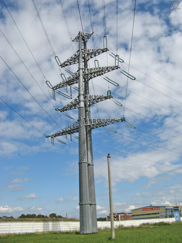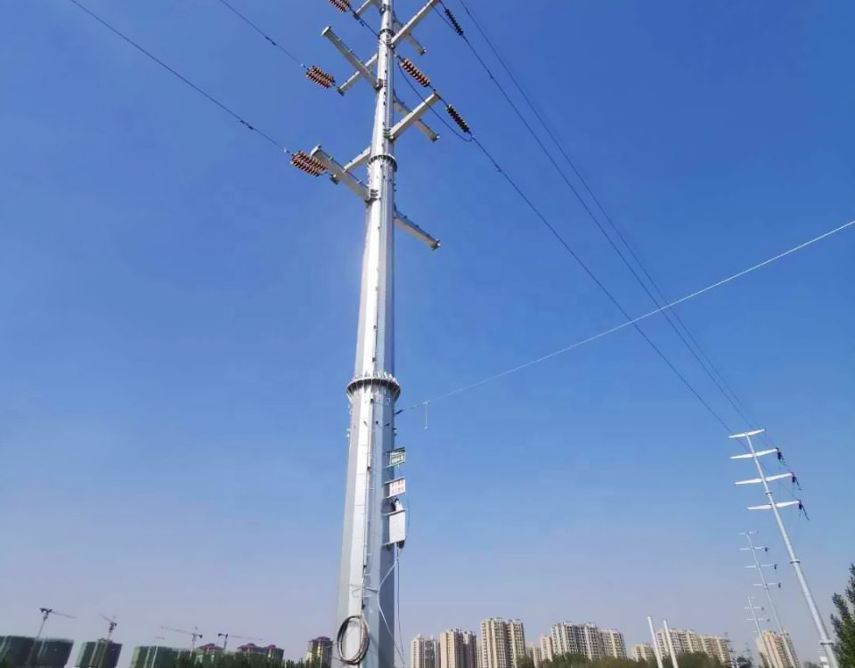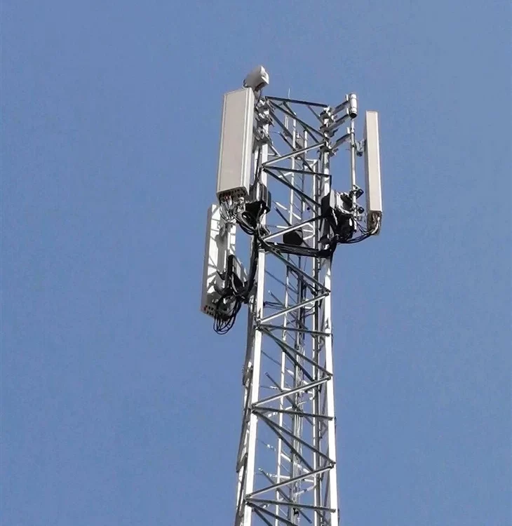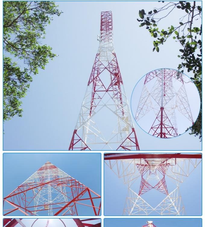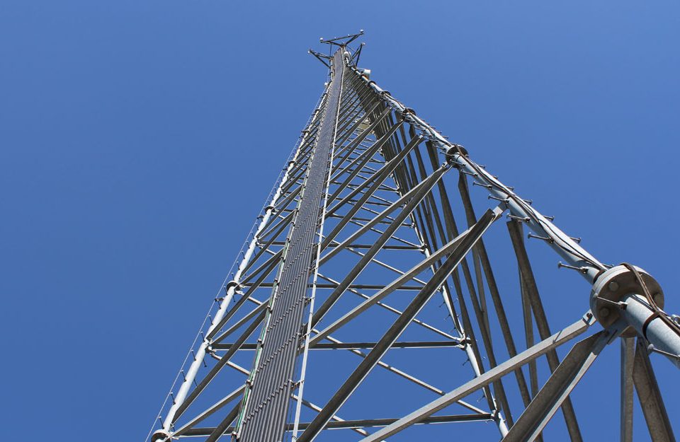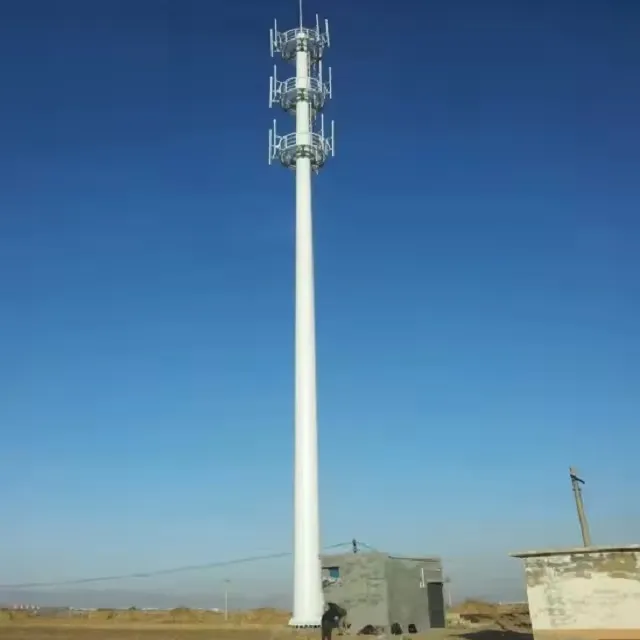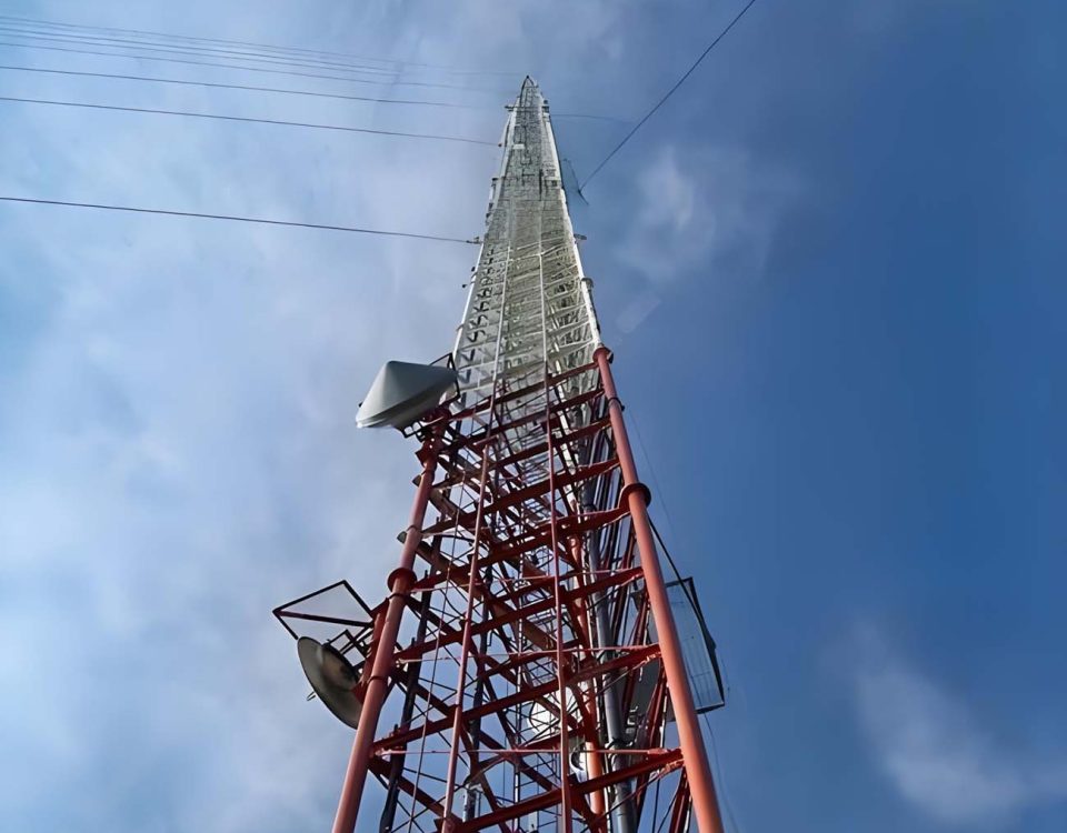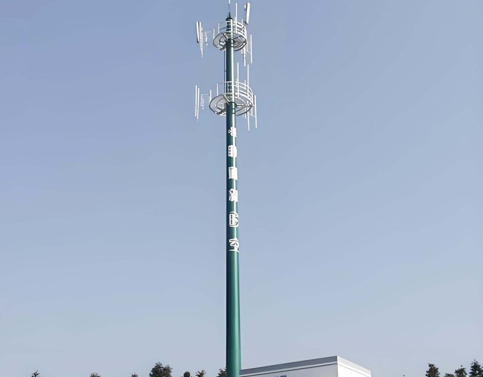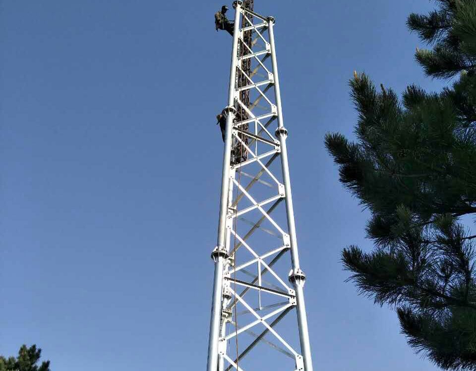
Communication Lattice Tower ,Manufacturing Installation
May 18, 2018
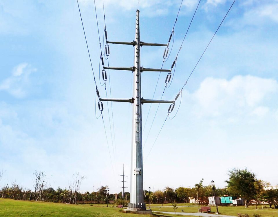
Tubular Tower manufacturer for Communication and Transmission
May 23, 2018The design of a monopole tower need the following Climatic condition:
Average grade of the atmosphere :
Minimum ambient temperature :
Maximum ambient temperature :
Average ambient temperature :
Relative humidity- maximum :
Average Annual Rainfall :
Maximum Wind velocity : km/hr or ( m/s)
Isokeraunic level :
Seismicity Coefficient :
Altitude or Terrain :
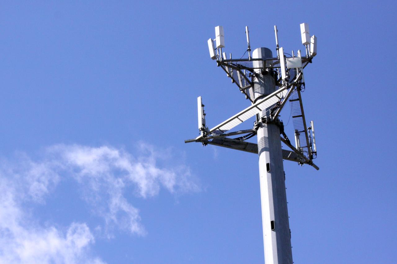
|
Tower Type |
Polygonal/Round Self-supporting Monopole |
|
Wind Speed |
100~240 KMPH |
|
Wind Pressure |
As per the customer request |
|
Steel Material |
Q235,Q345,Q420 |
|
Height |
10—50m |
|
Appearance |
Hot-dipped Galvanization or Painting |
|
Connection |
Overlap/Slip/Flange connection |
|
Design Code |
ANSI/TIA-222-G |
|
Production Standards |
GB/T 2694-2010 |
Height of Monopoles
Height of monopoles shall be determined in the under-mentioned way:
H = Gc + Sg + Li + Hc + Hg
Where,
H = total height of monopole
Gc = Necessary ground clearance of power conductors above ground or other objectives.
Sg = Maximum conductor sag
Li = Length of a suspension insulator set, but nil for a tension type monopoles.
Hc = Vertical spacing of upper conductor cross -arm spacing
Hg = Vertical spacing between upper conductor cross-arm and overhead earthwire.
The monopole Monopoles shall be provided with body extensions in a 3m step [3m, 6m, 9m and 12m] to a standard height for maintaining necessary conductor ground clearance mentioned in APPENDIX 1.A.2 on various ground profiles. Standard monopole structures are shown in Appendix 1.A.1 as well as insulation clearance diagram of conductors.
Monopole tower Design Span
The design of all towers shall provide for the following basic, wind and weight spans and shall be tabulated in form shown below. The table shall be submitted with the bids.
The term basic span means the horizontal distance between centers of adjacent supports on the level ground which the height of standard towers is derived with the specified conductor clearances to ground in still air at maximum temperature.
The term wind span means half the sum of adjacent horizontal span lengths supported on any one tower. It shall be indicated in the table Appendix 10. A.1
The term uplift weight means the weights of conductors and overhead earthwire supported upwards at any one tower for reinforcing strength of cross arms. It shall be indicated in the table of appendix 10. A.1
Monopole tower Design Loads
The following loads shall be applied in the design of towers:
(a) Wind Loads
– on power conductors and overhead earthwire :
(on the projected area of conductor or wire)
– On tower structures :
(on the projected area of structure members)
– On insulator sets :
(c) Maximum working Tensions of Conductor and Earthwire
– Power conductor Lynx :
– Overhead ground wire earthwire :
(c) Vertical Loads
– tower structures : actual weights of tower structures including accessories
– Power conductors : Weight of conductors of specified weight span with accessories
– Overhead earthwire : weight of specified weight span with accessories
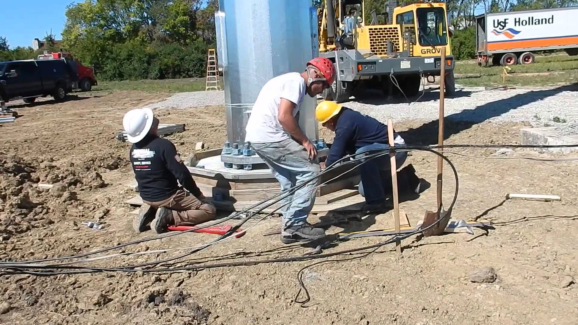
MONOPOLE TOWER MATERIALS
All steel shall comply with BS EN 10025 or BS EN 10210 as appropriate, unless otherwise specified and shall be suitable for all the usual fabrication processes, including hot and cold working within the specified ranges.
The quality of finished steel shall be in accordance with BS EN 10163. All steel shall be free from blisters, scale, laminations, segregations and other defects. There shall be no rolling laps at toes of angles or rolled-in mill scale.
Unless specified to the contrary the following grades of steel shall be applicable:
i. Mild steel shall be either grade S235JRG2 or S275JR.
ii. High tensile steel shall be grade S355JR for sections less than 20 mm thick and S355JO for sections greater or equal to 20mm thick, except for plates which shall be greater or equal to 40mm thick.

