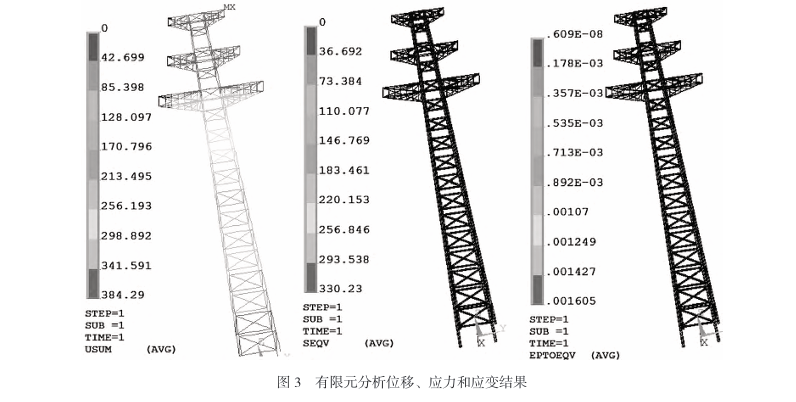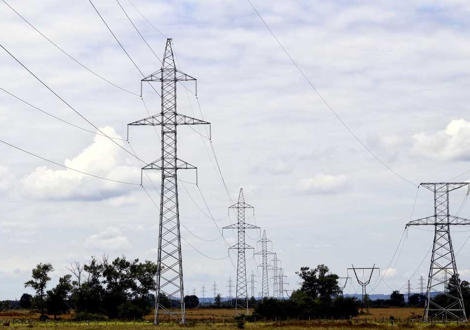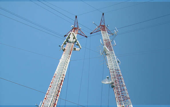
necessary parts of Radio masts and towers,communication towers
January 5, 2019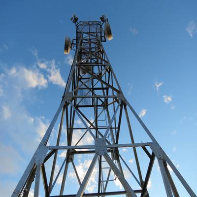
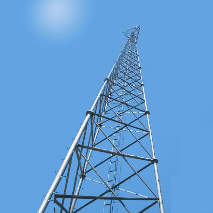
four legged angle iron /tube communication towers
January 12, 2019general information about guyed lattice mast,guyed lattice towers and masts
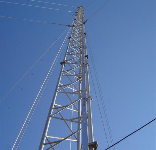
A lattice aluminium guyed mast system, designed for ultimate flexibility in design, manufacture and installation. The system comprises high quality extrusions in high grade 6082 TF aluminium alloy, using stainless steel bolts and all galvanised steel guys and guy fittings. The design allows low volume, high-density packing specifications for ease of shipping, and inland transportation (especially for remote sites). Sections can then be easily assembled on site.
- SCOPE
- This specification covers the technical requirements for the detailing and the detail design of guyed lattice masts, hereinafter referred to as “masts”, and must be read together with the Drawings, Conditions of Tender, Conditions of Contract and the Project Specifications forming part of this tender.
- Should any discrepancies exist between this Specification and the detail requirements for the specific project, the latter shall take preference.
- It is the responsibility of the Contractor to ensure that the Specifications and Drawings, which the tender is based upon and which are used in the execution of the works, are complete and of the latest issue.
- Any discrepancies and ambiguities in the documentation shall be reported to the MTC Representative prior to and in time to ensure that the work is executed in time and without delay.
- The design work for structures shall be undertaken by or under the control of a Registered Professional Engineer with adequate experience in the design field involved. The Contractor shall submit with the As-Built Documentation a certificate signed by the Professional Engineer concerned, accepting full responsibility for the design and of the Works. The certificate shall clearly show the engineer’s full name and registration number. Nothing in this specification shall limit the obligations, liabilities and responsibilities of the Contractor in any aspect of the design, manufacture and erection of these masts and all of which shall be in accordance with the OHSA & Design Code. The final responsibility for supervision and construction of the works to satisfy the overall performance requirements and design intent of the installation shall remain with the Contractor.
- The following Code of Practice shall form part of this specification:
SANS 0160 – 1989 : The general procedure and loadings to be adopted in the design of buildings
- The following Design Codes are applicable:
SANS 0225 – 1991 : Design and construction of lightning masts
SANS 0162 – 1993 : The use of structural steel
BS 8100 – 1: 1986 : Lattice masts and masts – Loading
BS 8100 – 2: 1986 : Lattice towers and masts – Guide and background
BS 8100 – 3: 1999 : Lattice towers and masts – Strength assessment of
members
BS 8100 – 4: 1995 : Lattice towers and masts – Loading of guyed masts
- Safety aspects for masts shall comply with:
ACT 6/1983 : Machinery and Occupational Safety Act of the Republic of South Africa which for the purpose of this contract shall be applicable in Namibia.
- AUTHORITY TO INSTRUCT CHANGES
- The *** Representative has the authority to instruct minor modifications to working drawings and details if and when not to the satisfaction and/or not in compliance with the specifications and such work shall be undertaken by the Contractor at the Contractor’s expense.
- Where such alterations to drawings are instructed on account of changes beyond the control of the contractor, e.g. say different antenna arrangements requested, the contractor will be compensated in accordance with the schedule of prices.
- Where such alterations to drawings are introduced on account of a difference in design approach between the contractor and the MTC Representative, the contractor will be compensated in accordance with schedule of prices.
- MATERIALS
- The materials for steel tubular sections shall comply with BS 4736 Grade 43A or higher grade depending upon availability of materials.
- All structural steel shall be grade 43A or 300W (or higher grades) and shall unless otherwise stated in the Project Specification be hot dip galvanised in accordance with the relevant specification and ready for painting to the recommendations of the Directorate of Civil Aviation. Properties of grades of steel to be used shall be clearly stated in the tender and the adequacy of the steel members and their grades shall be shown in the design.
- No commercial grade steel will be allowed in any structural member associated with the mast.
- All ancillary steelwork such as platforms, ladders, mounting brackets, wave guide bridges, etc. shall be galvanised all in accordance with the relevant specification, but shall not be painted.
- All bolts, washers, nuts etc. to be grade 8.8 (or higher grades) galvanised with corresponding provision for fit.
- The contractor shall submit certificates confirming the type(s) of steel used, the galvanizing and welding.
- Masts shall be galvanized unless specified otherwise in the Project Specification.
- Holding down bolts shall be grade 8.8 high strength bolts and galvanized.
- Guy ropes shall be galvanized (galvanizing certificate is to be submitted) and shall be of the steel core type listed as Galvanized IWRC.
- Anti temper devices shall be provided at ground level on all guy rope termination points in order to protect the mast against vandalism. Such devices shall not be part of the guy termination hardware but an enclosure with anti tamper bolts or secure locking devices, to enclose the guy termination hardware.
- ANTENNA CONFIGURATION AND DETAILS
- Antenna mountings shall be provided at the levels as shown on the drawings or in the Project Specification.
- Notwithstanding the information in the table below all masts from a height of 20m and above shall be designed for a mast loading capacity of a minimum of 14 m² spread over the top 10 metres of the mast.
- This loading is for antennas only. The antenna loading shall not be considered
to be shielding any sections of the structure.
- Antenna Configuration and Details:
|
|
|
|
|
|
|
ANTENNA TYPE |
NO. OFF |
POSITION |
PERMISSIBLE ROTATION |
|
|
|
GSM Panel antennas |
|
|
|
|
|
ALTERNATIVE : |
|
|
|
|
|
GSM Di-pole omni antennas on 1,2m long swivel mounting brackets with struts |
|
|
|
|
|
Microwave solid dish: |
|
|
|
|
|
1,2 diameter |
|
|
|
|
|
0,6m diameter |
|
|
|
- Antenna information is included in the Project Specification.
- PREFERRED CONFIGURATION OF MAST
- The configuration of a mast shall be triangular in plan.
- If preferred by the tenderer a cantilever top section up to 15m is acceptable.
- Allowance and provision is to be made for the lightning spike to be 3.5m above the top of the top antennas.
- DESIGN LOADS
7.1 TERRAIN CATEGORY AND EXPOSURE
Three mast options will be quoted for general use in the rollout. The terrain categories and site exposure are listed below.
- Sites at altitude shall be defined as “Highland Sites” will be designed for a site altitude of 1100 metres above sea level in Category 2. This definition does not include sites falling into the other 2 listed categories.
- Sites at an altitude between sea level to 1100m but not directly exposed to the sea front shall be defined as “Sea Level Sites” will be designed for a site altitude of 0 metres above sea level in Category 2. This definition does not include sites falling into the other 2 listed categories.
- The following mast type is categorized as “Topographical Mast”:
The is mast located on top of elevated positions after a sudden change in ground level, i.e. an existing building or a cliff face, This change in height is termed artificial base height. This category mast is located on hills with a slope of more than 17º (0,3 metre vertical climb for each 1 metre horizontal distance). If the mast is located. Should the mast be moved back along the top of the mountain by more than 5 times the escarpment height then the wind will be normalized and this condition will no longer be applicable.
The mast shall be designed 0 metres above sea level in category 1.
- WIND LOADING AND DEFLECTION / ROTATION
- Wind loads shall be in accordance with SANS 0160 and SANS 0225, as amended.
- Regional basic 3 second gust wind speed : 40 m/s
Wind load factor for serviceability limit state : 0,6
Wind load factor for ultimate limit state : 1,3
Mean return period : 50 years
- Maximum permissible deflection and : 2° maximum refer
rotation at antenna levels to Clause 5.2 and antenna data sheets
- Wind loading for the specified antenna(s) are published on the antenna data sheets.
These are defined in 5.2 above
- SUPERIMPOSED LOADS ON PLATFORMS AND LADDERS
7.3.1 Uniform superimposed load on platforms 2 kN/m²
Point load for hoisting of antennas 1,5 kN
7.3.2 Point loads on ladder sections 2 x 1,5 kN
7.3.3 Weight of feeder cables per running metre of mast 10 kg
- Effective wind area of wave guides per running
meter of mast 0,35 m²
7.3.5 Foundations : Maximum bearing capacity of soil 100 kPa
- LOADS DURING ERECTION
- Mast sections and components must be designed to withstand loads imposed during transport and erection and limitations concerning handling points etc. must be pointed out in the assembly and erection manual and be indicated on the tenderer’s drawings.
- MAST FOUNDATION, ANCHOR BLOCKS
ENERAL
The foundation design shall be carried out using Ultimate Loads, i.e. for stability as well as strength requirements.
- Foundations shall be designed for a maximum toe pressure as indicated in Table 7 of SANS 0225. Friction from soil adhesion to the sides of the concrete bases shall be ignored and the maximum probable water level shall be taken into account when calculating soil strength.
- Density of soil shall be taken as 1600kg/m³.
- For purposes of this tender document only, all tenderers shall assume a value of 100kPA for soil bearing value.
- Detailed construction drawings and bending schedules shall form part of the design.
- The foundation design and dimensions shall make provision for sufficient number of 110mm Ø PVC sleeve pipes for down conductors, power cables etc.
- DESIGN OF FOUNDATION AND ANCHOR BLOCKS
- The foundation and anchor blocks shall be designed to withstand the relevant imposed loads and will have factors of safety with regard to overturning, sliding, pull out etc. as set out in the relevant Codes of Practice.
- It is the designer’s responsibility to ensure that appropriate material and soil property factors are incorporated in order to guarantee a fully functional design.
- Appropriate testing shall be done on the anchors and anchor blocks as part of the quality control.
- MINIMUM FINISHING REQUIREMENTS
- The foundation and anchor blocks shall be detailed as such that no steel work is less than 150mm above ground level (e.g. the foundation and anchor blocks plinth shall protrude at least 150mm above ground level) and that no ponding of water will occur against any foundation / anchor block.
- All concrete shall have a minimum concrete strength of 30 MPa and shall be well compacted and cast against clean and straight shutter work (Degree of Accuracy II). All exposed concrete edges shall have a 35mm minimum chamfer.
The minimum concrete cover to reinforcement and or HD bolts shall be 75mm.
- 110mm µPVC sleeves with end caps for earthing, power cable etc. shall be provided in the foundation. No such services shall be installed on-surface.
Related posts
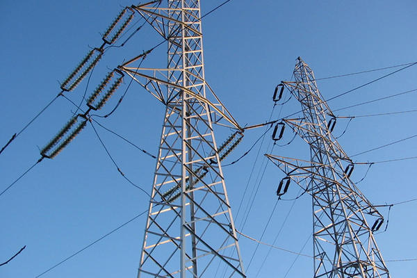
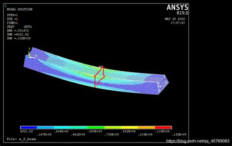
The analysis of the bearing capacity of a power transmission line steel tower highlights the complexity and importance of structural and foundation design. By understanding the interplay of loads, material properties, and environmental factors, engineers can optimize tower performance and ensure reliability in power networks. Tables and case studies further illustrate best practices and design considerations.

