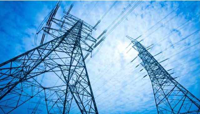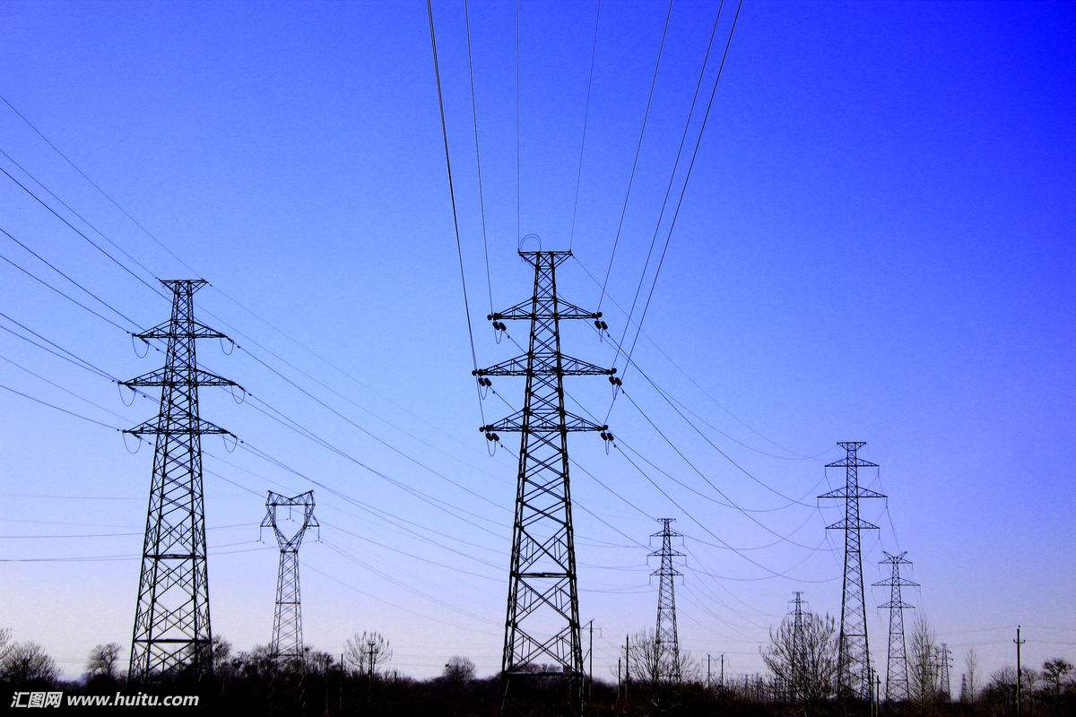
400KV Lattice Steel Tower Design Requirements and Design Spans for Support Locations ,Electric Transmission Line steel
March 31, 2018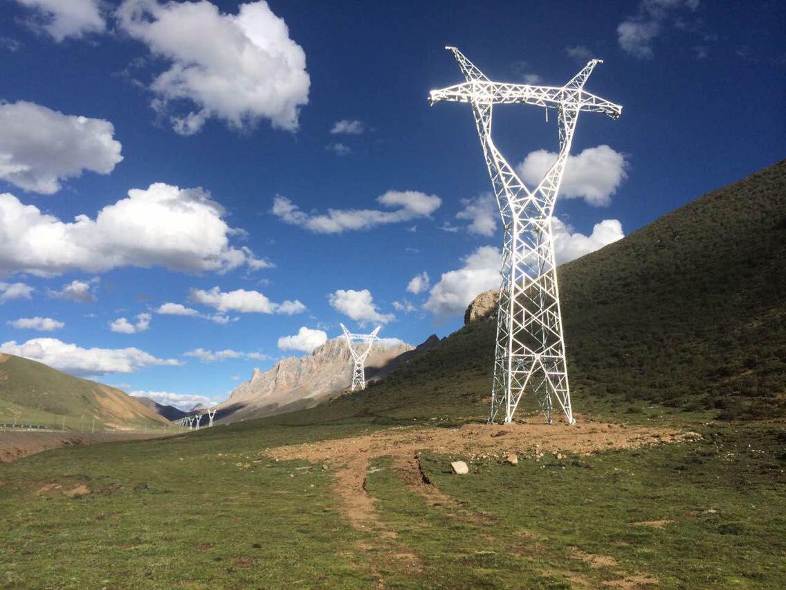
What are the types of High-Voltage Transmission Line ?
April 1, 2018Self-Supporting Steel Lattice Tower Sizing of Tower Members & Conductor Spacing and Clearances
B1.5.3 Sizing of Tower Members
Member and member connection design sizing shall be performed in accordance with the latest issue of Guide for Design of Lattice Steel Transmission Structures, ANSI/ASCE 10-97.
All tower members shall be sized using the member loads indicated on the tower calculation sheets to be submitted for approval. The bending moments (if any) of the tower members shall also be taken into consideration for member sizing.
The most efficient grades of steel and structural sections available shall be used to yield the lowest in‑place tower cost. The type and grade of steel shall conform to the latest applicable standards, specifications and recommended practices of the industry.
All tension members shall be designed to the full minimum yield point of the material.
Shear and bearing stress on bolts shall be computed using the nominal diameter of the bolt. Tensile stress on bolts shall be computed on net area of the bolt. The limit stresses in the design of bolts and nuts shall be subject to the Engineer’s approval.
The Contractor shall be responsible for ensuring that the towers are capable of withstanding the member stresses without permanent deformation in any parts of the tower.
The maximum ratio of effective unsupported length of steel members to the relevant radius of gyration (L/R) shall not exceed:-
- a) Leg members and cross arms chords: 120
- b) All other members carrying calculated stresses: 200
- c) Redundant members: 250
- d) Cross arm hanger: 300
- e) All other tension‑only members: 350
The thickness of tower members shall not be less than:
- a) Legs and main members of cross arm: 6 mm
- b) All other loaded members: 5 mm
- c) Redundant members: 4 mm
- d) Steel below ground: 6 mm
- e) Gusset plates: thickness of member connected plus 2 mm
- f) Minimum bolt diameter for leg members: 16 mm
The sizes of the angles used for tower members shall not be less than:
- a) Leg members: 50 x 50 x 6 mm
- b) All other loaded members: 40 x 40 x 5 mm
- c) Redundant members: 35 x 35 x 4 mm
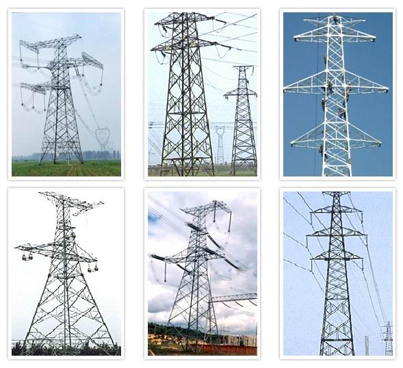
The maximum width of angle leg shall not exceed 16 times the thickness.
Flat bars and rods shall not be used for tower members.
The angle between any two members, which are connected to each other, shall not be less than 13o.
A maximum of three bolt diameters may be used for anyone tower type. All bolts of the same diameter used on more than one tower type, shall be of the same strength in order to avoid errors during erection. Bolts shall be provided with flat washers. Lock washers are not required as bolt threads will be punched to prevent loosening or theft. All bolts shall be supplied in sufficient quantities to allow for normal construction losses.
To allow for maintenance, all members that have an angle up to 300 with the horizontal shall be designed to resist a point load of 150 kg.
|
Self-Supporting steel lattice Towers for electric transmission line Design |
||
|
Structure Steel |
||
|
2. Grade |
Mild Steel |
High Tensile Steel |
|
GB/T 700:Q235B, Q235C,Q235D |
GB/T1591:Q345B, Q345C,Q3455D |
|
|
ASTM A36 |
ASTM A572 Gr50 |
|
|
EN10025: S235JR, S235J0,S235J2 |
EN10025: S355JR, S355J0,S355J2 |
|
|
3. Design Wind Speed |
Up to 250 km/h |
|
|
4. Allowable deflection |
0.5 ~1.0 degree @ operational speed |
|
|
5. Tension strength (Mpa) |
360~510 |
470~630 |
|
6. Yield strength (t≤16mm) (Mpa) |
355 |
235 |
|
7. Elongation (%) |
20 |
24 |
|
8. Impact strength KV (J) |
27(20°C)—Q235B(S235JR) |
27(20°C)—Q345B(S355JR) |
|
27(0°C)—Q235C(S235J0) |
27(0°C)—Q345C(S355J0) |
|
|
27(-20°C)—Q235D(S235J2) |
27(-20°C)—Q345D(S355J2) |
|
|
Bolts & Nuts |
||
|
9. Grade |
Grade 4.8, 6.8, 8.8 |
|
|
10. Standards for mechanical properties |
||
|
10.1 Bolts |
ISO 898-1 |
|
|
10.2 Nuts |
ISO 898-2 |
|
|
10.3 Washers |
ISO 6507-1 |
|
|
11. Standards for Dimensions |
||
|
11.1 Bolts |
DIN7990, DIN931, DIN933 |
|
|
11.2 Nuts |
ISO4032, ISO4034 |
|
|
11.3 Washers |
DIN7989, DIN127B, ISO7091 |
|
|
Welding |
||
|
12. Method |
CO2 Shielded Arc Welding & Submerged Arc Welding(SAW) |
|
|
13. Standard |
AWS D1.1 |
|
|
Marking |
||
|
14. Method of marking of the members |
Hydraulic Press Stamping |
|
|
Galvanizing |
||
|
15. Galvanization standard of steel sections |
ISO 1461 or ASTM A123 |
|
|
16. Galvanization standard of bolts and nuts |
ISO 1461 or ASTM A153 |
|
|
Test |
||
|
17. Factory test |
Tensile test,Elements analysis, Sharpy test(impact test), Cold Bending, |
|
|
Capacity |
||
|
18. Maximum Production Capacity |
50,000 TON per annum |
|
B1.5.1 Conductor Spacing and Clearances
The crossbeam arrangement and the dimensions shown on the tower outline drawings shall be assumed as the minimum requirements. It is the Contractor’s responsibility to supply cross beam extensions and insulator string linkages to ensure that minimum clearances are maintained.
The towers shall be designed to comply with the minimum net clearances between earthed metal and live conductor or fitting shown on the tower drawings.
The specified clearances between line conductors and all supporting steelworks shall be obtained on the assumption that the conductor 
may attain a position at any angle between 10o above and 20o below the horizontal for all types of tower. The down-leads on terminal towers shall be assumed to exit from tower at any horizontal angle in between 0º and 45º, from the longitudinal centerline at any vertical angle in between 0º and 45º.
The minimum clearances between the conductor at the maximum sag, at 75oC conductor temperature in still air, and ground or other objects shall be as follows:
|
Obstacles |
230 kV |
66 kV |
|
Normal ground and secondary roads |
8.0 m |
6.5 m |
|
Main roads, highways and railways |
9 |
7 |
|
Buildings |
not permitted |
not permitted |
|
Power supply circuits up to 400 KV |
5 |
4 |
|
Telecommunication lines |
5.25 m |
4.6 m |
|
Railways |
12.5 m |
10.5 m |

