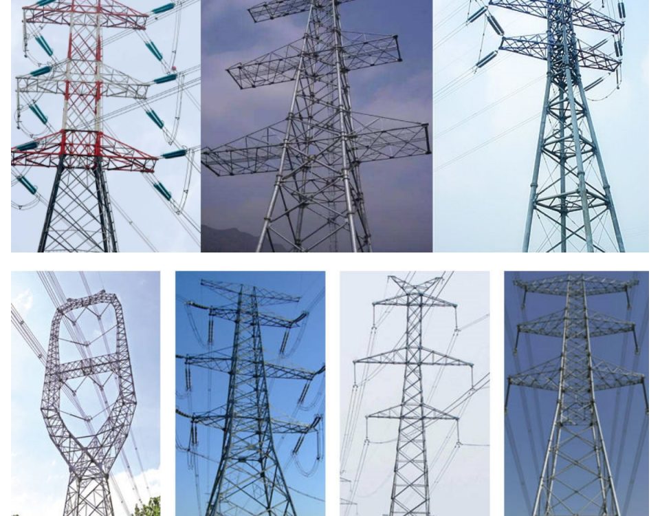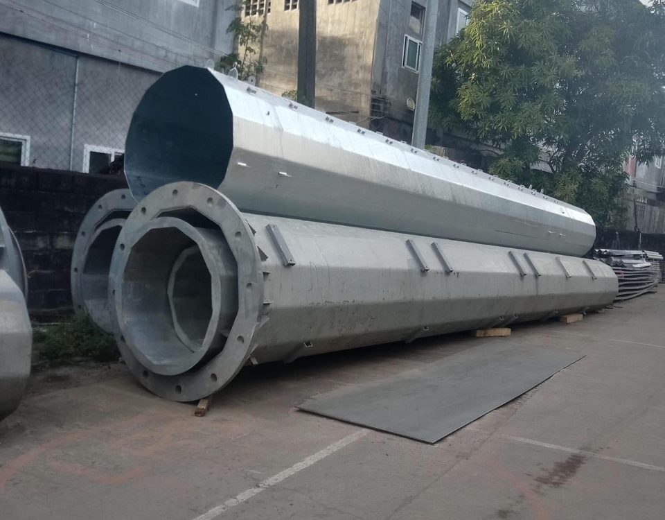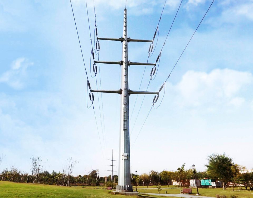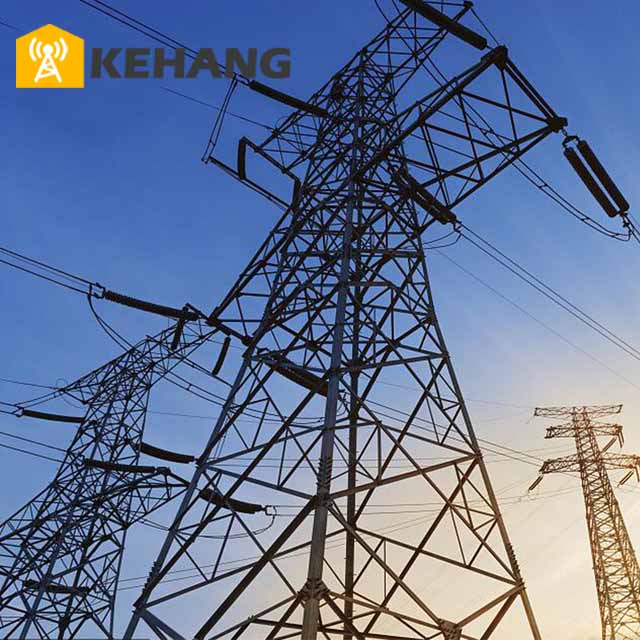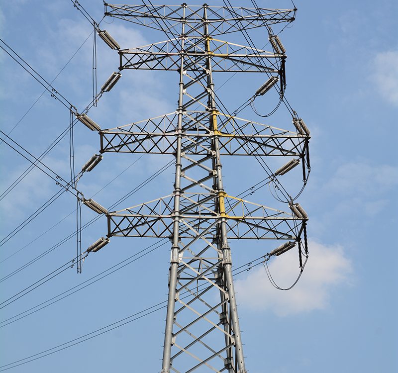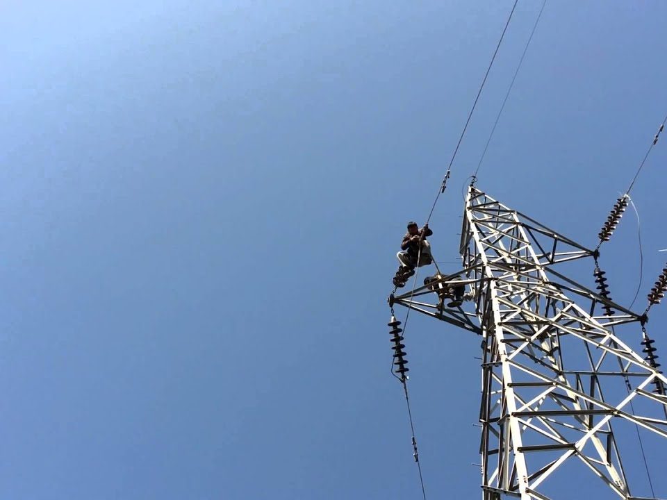
Galvanized Lattice Angle Steel Power Transmission Line Tower
October 24, 2018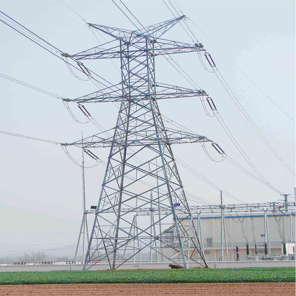
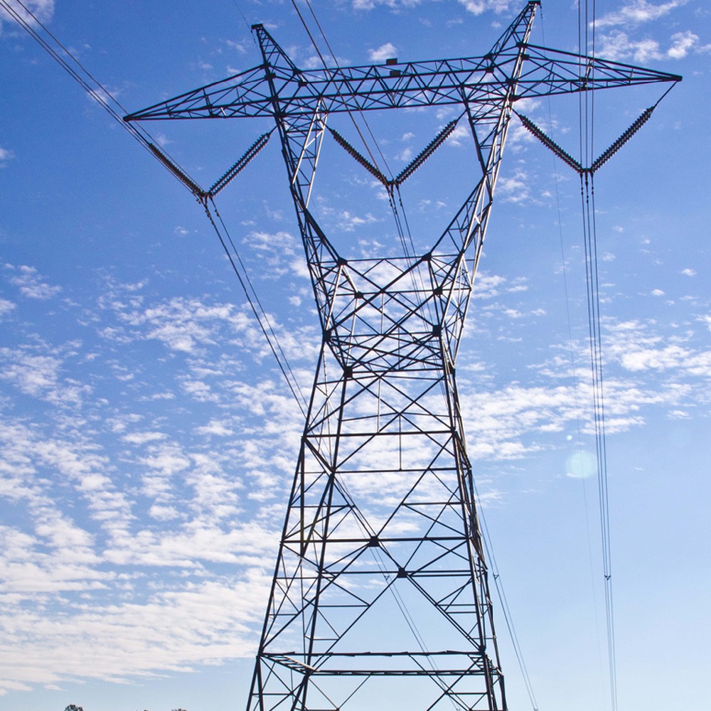
500 kv The High Voltage Electric Power Transmission Line Towers
October 29, 2018Steel Lattice Towers for Power Transmission up to 500 KV
STRUCTURAL STEEL
All rolled steel sections and plates shall be supplied in accordance with latest edition of ASTM A572 Grade 60 High Strength Low-Alloy Columbium-Vanadium Steel of Structural quality and GB/T 1591 Grade Q420, EN10025 S355J2 and GB/T 1591 Grade Q345, ASTM-A36 and GB/T 700 Grade Q235. In addition to requirements specified hereinabove and in the relevant standards, the offered steel shall withstand the following bend test requirements. However, procedure of bend test requirement shall be followed as per ASTM A370.
|
Type of Steel |
Thickness of Material |
Ratio of bend dia to thickness of specimen at 180⁰ |
|
Mild Steel |
For all thickness |
1.5 |
|
High Tensile Steel Grade 50 & 60 |
Up to 25 mm |
1.5 |
|
– |
Over 25 mm |
2.0 |
NUTS, BOLTS AND WASHERS
For all types of towers, all connections shall be secured by bolts, nuts, plain and spring washers. Hexagonal head bolts and hexagonal nuts shall be used. Only one plain washer and one spring washer per bolt shall be used.
Bolts shall be designed for only bearing and shear and the shank of all bolts except U-bolts shall extend completely through all connected members. When in position bolts shall project through the corresponding nuts neither less than 2 thread lengths nor greater than 10 mm. Members shall not bear on thread. Washers shall be used under all nuts. Bolts shall be free from fins, scale or other defects and the head shall be concentric and square with the shank. The diameter of the shank shall be full nominal size of the bolts. The ends shall be sharp and clean and of the proper contour.
All U-bolts shall be threaded for a sufficient length to take two standard nuts plus member and washer thicknesses.
Step bolts shall be provided as shown in the drawings.
Nuts shall be of sufficient height to develop the full strength of the bolt. Threads must not be torn or ragged and shall be of proper contour. The nuts shall fit the bolts after they have been galvanized so that they can be started and threaded by hand for the full length of the bolt thread.
The fit of the nut on to the bolt shall be such that no rocking of the nut will occur.
Nut and bolt of the same size shall be interchangeable. The bolt related dimensions for fabrication can be referred from DIN 7990 and nut according to DIN 555/ISO4034 The length of bolts shall be calculated to accommodate the thickness of one spring washer.
Material of bolts and nuts shall conform to ASTM A325 and/or ISO 898 standards.
The dimensions and material of spring lock washers shall be according to DIN127 and 128.
At least 5% surplus of bolts, nuts and washers shall be supplied to cope with losses and future maintenance.
The fabricated material shall not have physical properties inferior to those specified.
Bolt hole diameter shall not exceed the nominal diameter of the fastener plus 1.5 mm.
Ring fillers for the towers to be supplied in accordance with the dimensions given in the drawing no. NTDC/DESIGN/500KV/25. The material of ring filler shall conform to the properties of mild steel as per ASTM A36.
The minimum edge distances of bolts measured from the center of the bolt hole to the end of the member shall be as follows:
- For Compression Members: One and one-half bolt diameters.
- For Tension Members: In an end connection of not more than three bolts the end distance shall not be less than that given in (a) above or the following quantity, whichever is greater.
BIRD GUARD
To prevent birds perching immediately above the suspension/jumper insulator strings and fouling the same with dropping, suitable bird guards shall be provided on all types of towers. Saw type bird guard shall be provided on all the members/redundant members provided on top and bottom plan of cross arm/girder/boom/beam of suspension. Suitable provision of cleat / plate to be provided on all Suspension towers facilitating installation of bird guard after stringing.
WORKMANSHIP
The workmanship and finish throughout shall be of a quality equal to the best that is known to the art at the present time for this class of work. All work shall be carefully and accurately performed.
Members shall be cut to jig and holes shall be drilled or punched to jig. All holes shall be cylindrical and perpendicular to the member. Where necessary to avoid distortion of holes close to the points of bends, the holes shall be made after bending.
Fabricated steel work shall be in accordance with the drawings, and drilling, punching, cutting and bending shall be carefully and accurately performed to prevent any possibility of irregularities occurring which might introduce difficulty in the erection of towers or result in straining or distortion of the parts thereof.
BENDING
Tower members which are cold bent shall be normalized before galvanizing. Hot bending is preferred. The heating shall be done in an oven, so that the member is uniformly heated to a distance of approximately 150 mm either side of the bend point. Proper heat treating procedures shall be used in order to preserve the original physical properties of the metal. Bending of thick members shall be done in a hydraulic press with a suitable die to prevent buckling of an unrestrained leg. This process shall not be done under quick impact but through a slow moving press.
PUNCHING & DRILLING
Punching and drilling shall be done by methods designed to ensure accuracy. The center of any hole shall not vary more than 1.5 mm from its position neither shall the center to center distance of end holes in a group of holes vary by more than 1.5 mm. Plugging and welding of drilled holes shall not be permitted
Drills, punches and dies shall be sharp and true, and holes shall be round, true to size, and free from ragged edges and burrs.
Bolt holes shall have diameter 1.5 mm larger than the nominal diameter of the bolt.
It is preferable to have fabrication, punching and drilling carried out by means of a modern computer program technique.
All holes in material over 19.0 mm in thickness shall either be drilled or sub-drilled and reamed.
For high tensile steel (yield point equal or greater than 35 kg/mm²) holes shall be directly drilled at the definitive diameter or punched and reamed out. The difference between the punched and reamed diameter shall be at the minimum 4mm.
The die for all sub-punched holes, and the drill for sub-drilled holes, shall be at least 1.5 mm smaller than the diameter of the bolt. Drifting to enlarge holes shall not be permitted.
WELDING
Welding of structure members, filling or plugging of defective parts and mispunched holes shall not be permitted in tower fabrication. When holes are mispunched so that the net section of a member is decreased, the member shall be discarded. However, if welding cannot be avoided and is required in certain structure components, such as for rigging/attachment plates, prior written approval shall be obtained. In such cases welding procedures shall comply with ANSI/AWS D1.1M standards. Special care shall be taken regarding seal welding to ensure proper galvanizing and to avoid acid “bleeding” at pockets in structural assemblies.
GENERAL REQUIREMENTS FOR FABRICATION
The towers shall be fabricated having members’ sizes according to the approved drawings. No angle substitution shall be allowed for main leg, cross arm members and stubs. However member substitution for other tower members and redundant or secondary members may be allowed with the prior approval of the Engineer. In such a case the total number of member substitution would not exceed five (5)
ALLOWANCE FOR GALVANIZING
Allowance shall be made in gauge dimensions for the thickness of galvanizing and the possible formation of spelter fillets inside the angles so as to allow adequate erection clearance after galvanizing.
DRAWING
- Shop Details Drawings:
The detailed drawings shall show shop details including dimensions, shearing, punching, bevel cutting, bending and identification mark and weight for each member.
- Erection Drawings:
Erection drawings shall show the complete assembly of the structure indicating clearly the positioning of the members. Each member shall be piece-marked and the number and lengths of bolts shall be given for each connection. Shop details may be shown either by assembled sections (in place) or piece by piece (knocked down).
- Footing Installation Drawings:
Footing erection drawings showing each member with its identification mark, number and size of connection bolts and all dimensions required for the proper setting and positioning of stub angle footings with relation to the center of the structure.
- Bills of Material:
Bills of material for each tower shall show the quantity, type, size, length; weight and assembly mark for each member, including bolts, washers, plates and all fittings complete for each structure.
- Outline Drawing:
The Manufacturer shall prepare single line diagram from the detailed drawings which shall show the complete information like dimensions and member, angle sizes.
MANUFACTURER’S TESTS
The Manufacturer shall select two samples from each heat to carry out the following tests to satisfy him that the products comply with the specifications.
For Sections and Plates
- Chemical composition (Ladle Analysis)
- Tensile Tests
- Bend Tests
For Nuts and Bolts
- Proof Load test
- Ultimate Tensile Strength test
- Ultimate tensile strength test under eccentric load
- Cold bend test
- Hardness test
- Galvanizing test
For Washers and Ring Fillers
- Hardness test
- Galvanizing test
The Manufacturer shall maintain a record of tests carried out by him for examination by Inspector.
PROTOTYPE TOWER ASSEMBLY TESTING
One tower of each type of maximum height combination of body and leg extensions shall be shop assembled and vertically/horizontally erected on a suitable foundation bed to assure proper fit of all parts. Following should be kept in view during prototype tower assembly.
- Check carefully each member while assembling the prototype to revise and amend the detailed drawings according to the correct solution;
- For each member, the length, position of holes and interface with other members shall be checked accurately for proper fitness;
- Quantity of each member and bolts shall be carefully checked from the bill of materials when assembling the prototype;
- On the assembled tower eventual modifications shall be examined and performed, if necessary, without modifying the functionality of the structure; and
- Drawings and bill of materials, sizes of bolts, fillers etc. shall be put up-to-date accordingly, in all details before starting mass production.


