Galvanized Steel Lattice Telecom Tower
November 13, 2024
Difference Between Monopole Towers and Microwave Steel Towers
November 24, 2024Transmission Steel Tower – Finite Element Analysis and Optimization Design
Finite Element Analysis and Optimization Design of Transmission Towers
Abstract:
This paper uses the finite element optimization analysis method and the ANSYS software analysis platform to perform finite element analysis and optimization design on the transmission tower structure (taking the steel pipe tower as an example). In the structural analysis, based on the APDL language, a parametric finite element model is used to perform finite element analysis on the mechanical behavior of the initial design scheme under various working conditions, and the mechanical properties of the structure under different working conditions are evaluated. On this basis, the optimization design is introduced to optimize the initial design scheme. Under the premise of meeting the strength criterion, the total mass of the structure is optimized and reduced by 30%. In addition, this paper also proposes a general idea of tower design: empirical design-finite element structural analysis-optimization design, which improves design efficiency and saves costs, and can provide a reference for solving similar engineering problems. Keywords: finite element analysis; parametric design; transmission tower; structural optimization design.
Research background
Transmission towers are important load-bearing structures in power transmission equipment. Their safety and stability will directly affect the smooth operation of the entire power system [1]. The loads on transmission towers are also complex and diverse. Usually, the main loads include the deadweight of the conductors, wind force, and ice. Under the coupling of these different loads, the towers should have sufficient mechanical strength to ensure the normal operation of the transmission system [2]. Modern high-level transmission lines represented by ultra-high voltage transmission have increasingly higher requirements for the mechanical properties and safety of towers. Therefore, it is of great practical significance to conduct structural strength analysis on transmission towers to avoid serious damage to the towers. Static mechanical analysis of towers is the basis for studying their mechanical properties. The traditional tower structure design method is empirical design, that is, the designer first designs an initial scheme according to relevant requirements, and then manually checks the structure. If it does not meet the requirements of mechanical properties, the structure is modified again and checked again, and this process is repeated until the final design scheme is obtained. This design method is inefficient, time-consuming, and highly dependent on the experience level of the designer. This method is even more difficult to work in the face of increasingly complex and diverse structures of transmission towers. With the development of modern computational mechanics, finite element simulation analysis has greatly improved the accuracy and efficiency of analysis. This paper selects ANSYS software as the analysis platform to perform finite element analysis and optimization design on transmission towers.
1 Finite Element Analysis of Transmission Tower Structure
1.1 Research Object
There are many types of transmission tower structures. This paper intends to analyze the structure of a newer type of transmission tower structure, the four-tube steel pipe tower. This tower is a 220kV single-circuit 50° angle steel pipe tower. Its main and crossbars are made of steel pipes. The tower is 50m high, and the position and width of the three crossarms in the height direction are known. In addition, all other information is uncertain, such as the spacing of crossbars, the spacing of crossarm support rods, material parameters, main materials, crossbars, and angle steel cross-sectional dimensions. In view of this situation, empirical design should be carried out first to determine the basic form of the tower, obtain the initial design scheme, and then conduct finite element analysis on this scheme. Before conducting finite element analysis, it is necessary to simplify the structure and only conduct finite element analysis on the components that reflect the main mechanical properties of the structure. For example, in the transmission tower, the connection bolts, connection plates and attachments can be ignored first, and the tower frame can be analyzed, which can not only focus on the stress behavior of the structure, but also avoid wasting too much computing resources.
1.2 Geometric Modeling
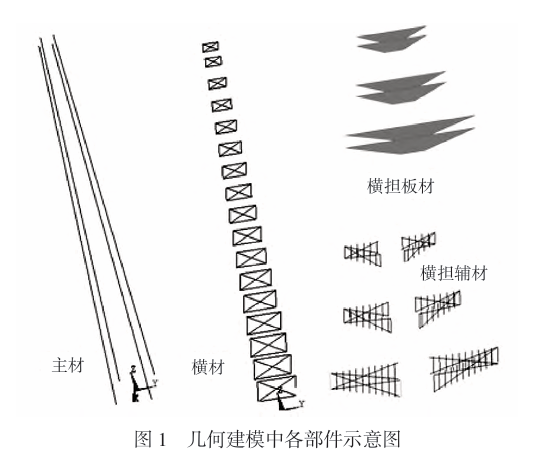
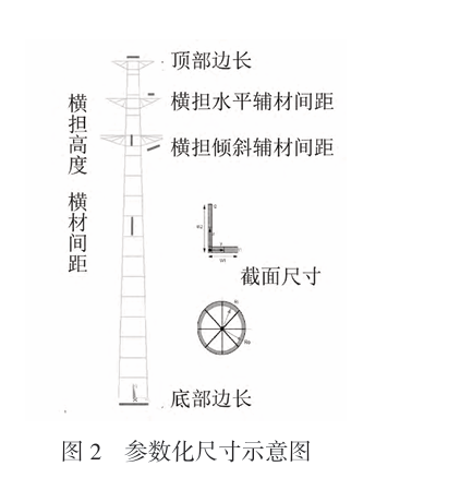
Once the fixed parameters are input, the geometric shape and main mechanical parameters of the finite element model are basically fixed. It is mainly used for mechanical analysis of set parameters, and cannot be used for the optimization of key design variables. The universality is poor. This paper focuses on the optimization of the main design parameters of the transmission tower. Therefore, it is necessary to adopt the parametric finite element modeling method. According to the idea of parametric modeling, based on the APDL language, the entire tower structure module is divided into four parts in the geometric structure: main material, cross material, cross arm plate and cross arm auxiliary material. The geometric model is established in turn, and finally the overall model is obtained by “general assembly”. The schematic diagram of modular modeling is shown in Figure 1. In the modeling process of this paper, some geometric dimensions are parameterized, such as crossarm height, crossbar spacing, top side length, horizontal crossarm auxiliary material spacing, inclined crossarm auxiliary material spacing and cross-sectional dimensions. The schematic diagram of parameterized dimensions is shown in Figure 2. In the initial design scheme, all steel materials are set to Q235 steel with a yield strength of 235MPa. The finite element software itself only performs numerical calculations. In terms of unit system, the user can set a closed unit system by himself. For convenience, this paper uses the mm-ton-N-MPa unit system in analysis.
1.3 Mesh division
The transmission tower structure has many connection forms, and the cross-sectional shapes of the components are diverse, and the orientation and overall stress conditions are relatively complex. The conventional finite element analysis model simplifies the tower into a spatial truss model. The main problems are as follows: First, only the axial tension and compression of the main material are considered, but in reality, in addition to axial tension and compression, the main material of the tower also bears complex bending moments and torques. Second, at the node connection, the simplified hinge cannot transmit bending moment. The actual tower connection is usually connected by bolts, welding, etc. The specific rigid connection characteristics are that bending moment, shear, etc. can be transmitted at the connection, while the simplified hinge cannot fully reflect the actual rigid connection. Third, the model cannot fully display the cross-sectional stress of the component, and usually only displays the node stress of the finite element model. According to the stress characteristics of the transmission tower, this paper considers the complex effects of tension, compression, bending, and torsion on the rods, and uses 3D beam elements (beam189) for modeling. At the same time, the differences in the cross-sectional shape and orientation of each rod are considered, and the cross-sectional shape and direction are defined. In the post-processing of the finite element analysis results, the cross-sectional stress is extracted, not just the node stress. Considering the complex stress conditions of the cross-arm plate, the shell element (shell63) is used for meshing. The 3D beam unit-shell unit finite element analysis model in this paper can avoid the problems of the truss model, reflect the complex stress conditions of the main materials and the rigid connection of the connection points, fully reflect the cross-sectional shape of the components and display the cross-sectional stress of the components, and can fully reflect the overall stress characteristics of the transmission tower.
1.4 Boundary conditions
The loads borne by the transmission tower are relatively complex, mainly including self-weight, wind load, the effect of the conductor on the tower, and attachments (ice coating, hardware, etc.). In addition, special situations such as line breakage need to be considered. In the design of the tower, the calculation of loads is relatively mature, and there are many special calculation programs that can calculate the stress conditions of the tower under various working conditions and meteorological conditions, and then equivalent to the relevant points of the tower. This paper uses the “MYLHZ full stress load calculation system” to calculate the stress conditions of the tower under various working conditions. It should be noted that this program can calculate the stress conditions of hundreds of working conditions. After preliminary empirical analysis, this paper finally selected 5 relatively severe working conditions for detailed analysis. These 5 working conditions are as follows. Working condition 13: strong wind, unbalanced tension, 0-degree wind; working condition 16: strong wind, unbalanced tension, 90-degree wind; working condition 25: ice cover, balanced tension, 0-degree wind; working condition 78: broken wire, unbalanced tension, no wind, broken conductor, 1, 3; working condition 87: installation, adjacent gear not hung, 90-degree wind, traction conductor 1. Relative force boundary conditions, the displacement constraint of the tower is relatively simple, that is, the bottom 4 points are fully constrained.
1.5 Analysis and discussion of finite element model results
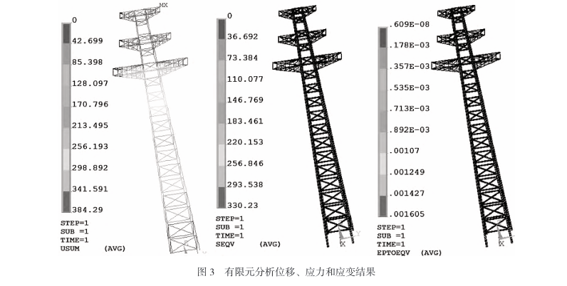
This paper mainly based on the strength criterion when conducting finite element analysis on the initial scheme, that is, the maximum equivalent stress of the structure cannot exceed the yield strength. In this case, the structure is considered safe, otherwise it is considered that the possibility of structural failure is high. After analysis, it was found that under working condition 25, the maximum displacement of the tower reached 384mm and the maximum equivalent stress was 330MPa, which exceeded the yield value of the material 235MPa. Therefore, the possibility of structural failure under this working condition is relatively high. See Figure 3 for details.
2 Optimization design of transmission tower structure
2.1 Introduction to optimization design
Optimization design is a technique for finding the optimal design solution, which is to find the optimal design solution that can achieve the design goal under the constraints. The international large-scale software ANSYS provides an optimization design module and all parameterized ANSYS options can be used for optimization design. The main calculation process of optimization design is as follows: first, initialize the variables and establish a parametric model. Then, according to the objective function and constraints, combine the design variables to perform finite element calculation and analysis, use the zero-order optimization method to perform global search and optimization, and then judge the convergence of the results. If convergence, the calculation ends and the optimization result is obtained; if not, adjust the design variables and recalculate until convergence..
2.2 Setting of optimization parameters
According to the basic idea of optimization design, the three key points of optimization design include the selection of design variables, constraints and objective functions. Since the basic form of the tower structure has been determined, but there are still many parameters that can be designed, some key parameters are selected for optimization. This paper selects 16 variables such as bottom side length, top side length, crossbar spacing, and cross-sectional dimensions as design variables. The optimization is based on the strength criterion, so the constraint selection is relatively simple, that is, the maximum cross-sectional stress of various units cannot exceed the yield strength of 235MPa.
2.3 Objective function selection
Initial structure
The objective function of this paper is relatively simple, that is, the total mass of the structure. The purpose of optimization is to reduce the total mass of the structure. According to the results of finite element analysis of each working condition, in the five working conditions, the degree of danger decreases from working condition 25 to working condition 78 and finally to working condition 87. For the sake of prudence, this paper selects the most dangerous working condition (working condition 25) as the optimization working condition. Under this working condition, the optimization result will make the structure tend to be safer.
2.4 Setting the optimization algorithm
The ANSYS optimization algorithm converts the constrained optimization problem into an unconstrained optimization problem by approximating the objective function or adding a penalty function to the objective function. There are usually two types of algorithms, zero-order algorithm and first-order algorithm [3]. The zero-order algorithm is also called the direct method, which does not use the first-order partial derivative information. The first-order algorithm is also called the indirect method, which uses the first-order partial derivative information. Generally speaking, the first-order algorithm has a large amount of calculation and a high precision of the calculation result, while the zero-order algorithm has a small amount of calculation, a fast operation speed, and a low precision of the result, but it can basically solve most projects. This paper chooses the zero-order algorithm. The zero-order algorithm fits the response function of the design variables, state variables, and objective functions based on a certain number of samplings, and then seeks the optimal solution. This paper sets the loop control parameter to 50. After setting the design variables, constraints, objective functions, optimization algorithms and other parameters, iterative optimization is performed, and the optimization results are finally obtained, as shown in Table 1. According to Table 1, under the premise of meeting the strength criterion, the total mass of the structure is reduced to about 25t, with a reduction of up to 30%.
3.5 Structural optimization design ideas
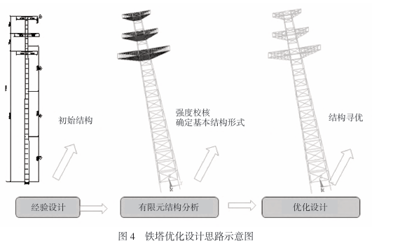
From the above structural finite element analysis to structural optimization design, a universal idea can be summarized. The first step is to obtain the initial design scheme through empirical design. According to the tower design requirements and design conditions, the basic structural form and basic parameters of the transmission tower are first determined based on experience. The rationality of the initial design scheme depends on the design experience of the designer. The second step is to use finite element analysis to check the strength. Improve the unreasonable parts that may exist in the initial design scheme. The third step is structural optimization design, and find the optimal structure under the premise of meeting the constraints. The schematic diagram of this optimization idea is shown in Figure 4. The traditional “preliminary design-analysis and verification-return modification-analysis and verification” empirical design method is inefficient, time-consuming, and the structure may be redundant and uneconomical. The optimization design idea proposed in this paper takes empirical design as the original basis, gives full play to the subjective creativity and design experience of designers, and is based on finite element simulation analysis and optimization. It uses modern optimization algorithms and uses the powerful computing power of computers to perform iterative analysis. It can find the most optimized structure in a shorter time, greatly improves the design efficiency, optimizes the design results, saves time and resource costs, and has good economic benefits.
3 Conclusion
This paper establishes a finite element analysis model of a transmission tower (four-tube tower), based on which finite element analysis and structural optimization design are carried out, and finally a reference design scheme is obtained. The finite element model is based on the APDL language, realizes parametric control, has a high degree of automation, and can adapt to different tower heights, crossbar positions, crossarm positions, various cross-section parameters and material parameters of tower types, providing a reference for the analysis of similar structures in the future. In addition, this paper also proposes a general idea of tower design, namely, empirical design-finite element structural analysis-optimization design, which improves design efficiency and saves costs, and can provide a reference for solving similar engineering problems.


